background image

- 18 - 


B

ATTERY 

B

OX 

I

NSTALLATION


ATTENTION: 
CONFIRM ON THE SPECIFICATION LABEL THAT THE VOLTAGE FROM THE BATTERY BOX IS THE 
SAME AS THAT ALLOWED BY THE UPS. 
THE CONNECTION BETWEEN THE UPS AND THE BATTERY BOX MUST BE MADE WITH THE BATTERY 
BOX FUSE HOLDERS OPEN. 
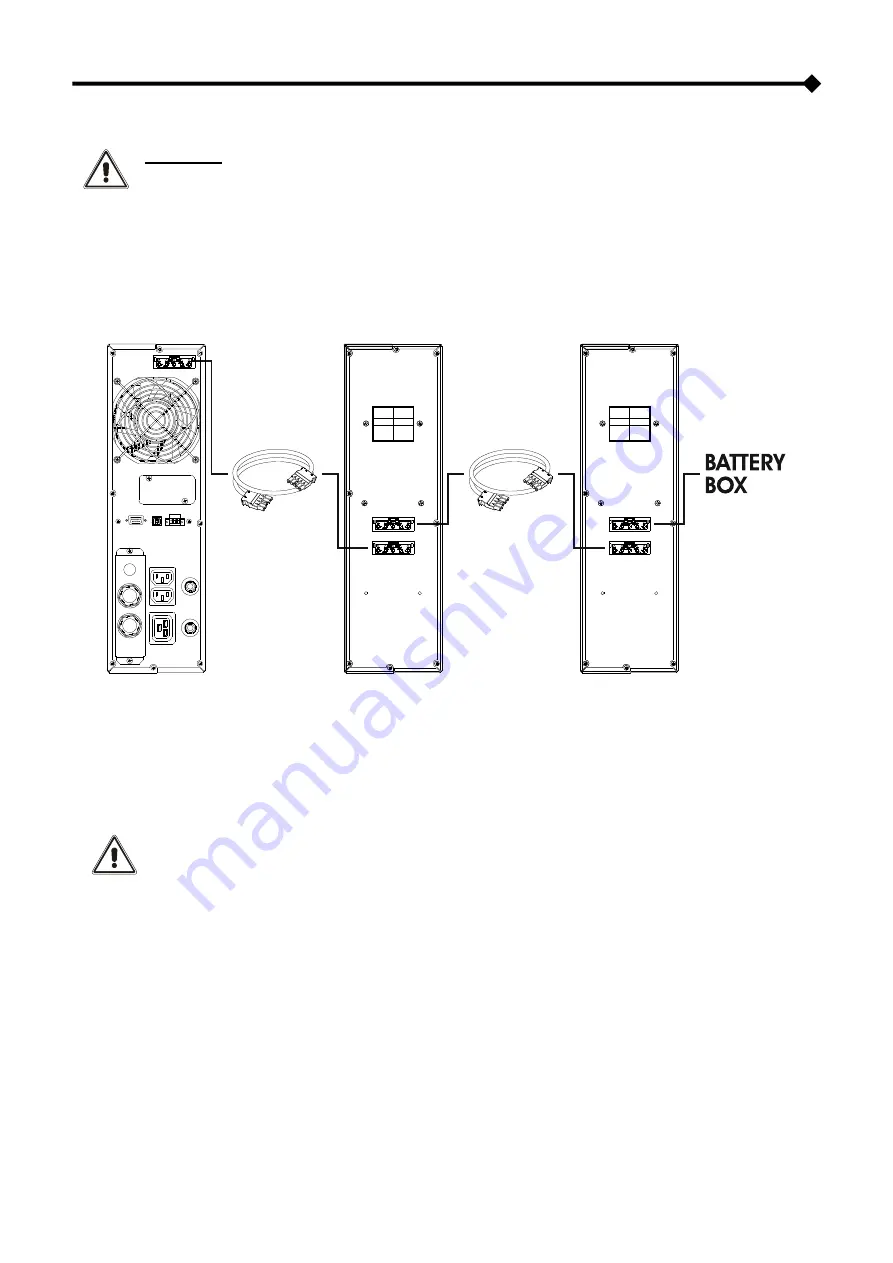
CONNECT THE CABLE BETWEEN THE UPS AND BATTERY BOX. 
CLOSE THE FUSE HOLDERS ONLY IF THE UPS IS POWERRED ON OR IN STAND-BY CONDITION. 

 
Battery boxes can be installed in series for extended runtimes. Connect the Battery Boxes in series as shown in the figure 
below: 


C

ONFIGURING THE RATED BATTERY CAPACITY


Before installing one or more Battery Boxes, the UPS must be configured in order to update the rated capacity value (total Ah 
UPS's internal bat external batteries) using the dedicated configuration software. 
The Battery Box must only be installed while the UPS is switched off and disconnected from the mains power supply. 


CAUTION: 

The connection cables cannot be extended by the user. 
The maximum length of the connecting cables between the UPS (without internal batteries) and the Battery 
Box is 3 meters. 
After connecting the UPS to its Battery Boxes, insert the fuses and turn the Battery Box battery isolators 
(SWBATT) to the ON position. 
It is recommended that you do not connect more than 5 Battery Boxes in cascade to a single UPS. To increase 
capacity, we recommend installing a Battery Box with higher battery capacity. 


Summary of Contents for Sentinel Dual SDU 4000

Page 1: ......

Page 2: ......

Page 3: ...ducts pursue the objectives defined in the environmental management system developed by the company in compliance with applicable standards No hazardous materials such as CFCs HCFCs or asbestos are used in this product When evaluating packaging the choice of material has been made favouring recyclable materials For correct disposal please separate and identify the type of material of which the pac...

Page 4: ... 16 EXTERNAL PROTECTIVE DEVICES 17 CONNECTION CABLES CROSS SECTION DETAILS 17 CONNECTIONS 17 BATTERY BOX INSTALLATION 18 CONFIGURING THE RATED BATTERY CAPACITY 18 USE 19 CONNECTIONS AND SWITCHING ON FOR THE FIRST TIME 19 SWITCHING ON FROM THE MAINS 19 SWITCHING ON FROM THE BATTERY 19 SWITCHING OFF THE UPS 19 DISPLAY PANEL MESSAGES 20 UPS STATUS MESSAGES 20 MEASUREMENT DISPLAY AREA 21 OPERATING MOD...

Page 5: ...ORING AND CONTROL SOFTWARE 26 CONFIGURATION SOFTWARE 26 UPS CONFIGURATION 27 COMMUNICATION PORTS 29 RS232 CONNECTOR 29 COMMUNICATION SLOT 29 TROUBLESHOOTING 30 ALARM CODES 32 FAULT 32 LOCK 33 TECHNICAL DATA 34 ...

Page 6: ...le for many different applications from IT to security SENTINEL DUAL can be installed as Tower floor standing or Rack ideal for network and server rack applications SENTINEL DUAL is available in the 4000 VA version and it was developed to be powered by a single phase input network The batteries are user replaceable without switching off the equipment and without interruption to the load Hot Swap E...

Page 7: ... 7 UPS VIEWS FRONT VIEW With front panel Without front panel Extractable rotatable display plate 1 0 Switch Release slits Battery pack connector Removable front panel Battery pack retention panel ...

Page 8: ...232 communication port Cooling fan EnergyShare sockets 10A max and overcurrent protection Communication Card Slot IEC sockets 16A max and overcurrent protection Remote control terminal Protection box for IN OUT connection USB communication port ...

Page 9: ... level indicator ON button Configuration area STAND BY button Maintenance request Regular operation Timer Mains operation Measurement display area Battery operation Stand by alarm Load powered by bypass EnergyShare Battery charge indicator ...

Page 10: ...ckouts The number of batteries contained can vary according to the type of UPS for which the BATTERY BOX is intended It is therefore necessary to take great care to ensure that the battery voltage of the BATTERY BOX is the same as the voltage permitted by the UPS Several BATTERY BOXES can be connected in series to achieve a longer extended runtime Front view Rear view Extractable rotatable Battery...

Page 11: ...ents The package must contain UPS and eventual BATTERY BOX Safety manual Quick start guide Download card USB cable Support feet extensions Handles for rack installation Handle screws Connection cable UPS Battery Box only for Battery Box Support feet extensions only for Battery Box Fuses only for Battery Box ...

Page 12: ...40 C and the UPS must not be positioned in places which are exposed to direct sunlight or to hot air The recommended operating temperature for the UPS and the batteries is between 20 and 25 C The actual operating life of the batteries is 5 years on average with an operating temperature of 20 C If the operating temperature reaches 30 C the operating life is halved This is a category C2 UPS product ...

Page 13: ...TTERY BOX IS DISCONNECTED FROM THE UPS FROM ANY OTHER BATTERY BOXES AND WITH THE BATTERY ISOLATOR OPEN Once removed from the packaging the UPS is already preset for installation in the tower configuration To complete the configuration simply mount the UPS on the two support feet Each leg consists of three parts connecting to each other at joints To put a leg together proceed as shown in the figure...

Page 14: ...LOAD THE BATTERY BOX IS DISCONNECTED FROM THE UPS FROM ANY OTHER BATTERY BOXES AND WITH THE BATTERY ISOLATOR OPEN For the Battery Box version each foot is composed of four parts two supports and an extension Assemble two feet as indicated in the figure below Slide the UPS and the Battery Box into the two supports For any additional Battery Boxes repeat the sequence of operations shown above ...

Page 15: ...nd gently pull it away from its position just enough to be able to rotate it ATTENTION the panel must be removed carefully DO NOT ATTEMPT IN ANY WAY TO REMOVE THE PANEL FROM THE UPS 2 Rotate the panel 90 counter clockwise and reinsert it carefully into the special housing 3 At this point with the UPS or Battery Box in the horizontal position secure the handles using the screws provided as shown in...

Page 16: ...ngth of the stripping refer to the paragraph Connection cables cross section details NOTE To remove the wire insert a flat blade screwdriver into the clamp slot above the wire inlet 4 Secure the cables with the cable glands 5 When the installation is complete close the drawer cover and secure with the screws Terminals cover installation INTERNAL PROTECTIVE DEVICES OF THE UPS Located within the UPS...

Page 17: ...nted activation Differential type B CONNECTION CABLES CROSS SECTION DETAILS The minimum cross section of the input and output cables on terminals is 4sqmm The stripping lenght of the cables must be 15mm The cross sections refer to bare cables without lugs with a maximum length of 10 meters CONNECTIONS The first wire to be connected is the protective earth wire which is to be inserted in the termin...

Page 18: ...ery Boxes the UPS must be configured in order to update the rated capacity value total Ah UPS s internal batteries external batteries using the dedicated configuration software The Battery Box must only be installed while the UPS is switched off and disconnected from the mains power supply CAUTION The connection cables cannot be extended by the user The maximum length of the connecting cables betw...

Page 19: ...AINS 1 Press the ON button for 1 second After pressing it all the icons on the display light up for 1 second and the UPS beeps 2 Switch on the equipment connected to the UPS When switching on for the first time only after 30 seconds check that the UPS is operating correctly 1 Simulate a blackout by disconnecting power to the UPS 2 The load must continue to be powered the icon on the display must l...

Page 20: ...ls Fixed Indicates that the loads connected to the UPS are powered by the bypass Dynamic Indicates the estimated percentage charge of the batteries Dynamic Indicates the percentage of load applied to the UPS compared with the nominal value Flashing Maintenance is required Contact the support centre Fixed Indicates that the timer is active programmed switch on and switch off The timer can be activa...

Page 21: ...sponding alarm Some examples are shown below GRAPHIC EXAMPLE 1 DESCRIPTION GRAPHIC EXAMPLE 1 DESCRIPTION Mains voltage Residual battery autonomy Mains frequency Battery charge percentage UPS output voltage Total battery voltage Output voltage frequency Applied load percentage Fault Alarm 2 the corresponding code is displayed Current absorbed by the load Lock 2 the corresponding code is displayed U...

Page 22: ...rom the waveform of the mains voltage maintaining the output frequency synchronised to the mains within a configurable range Outside this range the UPS output de synchronises from the mains supply moving to the nominal frequency in this condition the UPS cannot use the bypass In order to optimise performance in ECO mode the load is normally powered by the bypass If the mains goes out of the permit...

Page 23: ... them REMOTE CONTROL TERMINAL BOARD and R E P O The remote control terminal allows for implementation of the REPO function Remote Emergency Power Off and to remotely switch ON and switch OFF the UPS The UPS is provided by the manufacturer with the REPO terminals short circuited For installation remove the short circuit and connect to the device s normally closed contact In case of an emergency if ...

Page 24: ...E BATTERY PACK IS VERY HEAVY USE EXTREME CAUTION WHEN REPLACING IT 1 Set the UPS to bypass mode manually by pressing the ON SEL buttons for 4 seconds see paragraph entitled Manual Bypass The display should show the message C02 NOTE in this condition the load is powered by bypass 2 The battery pack is positioned behind the UPS front panel Remove the front panel as shown in the figure below A Remove...

Page 25: ...atteries see the label located on the battery pack near the connector 5 Insert the new battery pack into the compartment sliding it into the UPS Put the battery pack retention panel back in position and secure it with the two screws removed previously Connect the battery pack cable to the UPS and close the front panel Set the UPS to normal operation mode by pressing ON SEL for at least 4 seconds 6...

Page 26: ...d network messages automatically when certain events selected by the user occur INSTALLATION OPERATIONS 1 Connect one of the UPS s communication ports to one of the PC s communication ports using the cable supplied 2 Download the software from the web site www riello ups com selecting the specific operating system 3 Follow the installation program instructions 4 For more detailed information pleas...

Page 27: ...n Disabled without input output synchronisation Power off due to minimum load Automatic UPS power off in battery operation mode if the load is lower than 5 Disabled Enabled Disabled Autonomy limit Maximum battery operation time Disabled Disabled complete battery discharge 1 65000 sec in 1 sec steps Battery low warning Estimated autonomy time remaining for the battery low warning 3 min 1 255 min in...

Page 28: ...n ECO mode Bassa 200V Alta 253V Low 180 220 in 1V steps High 240 264 in 1V steps Intervention sensitivity for ECO Selects the intervention sensitivity during operation in ECO mode Normal Low Normal High Power on delay Waiting time for automatic switching back on after mains power returns 5 sec Disabled 1 255 sec in 1 sec steps Remote power on off function Select the feature associated with the rem...

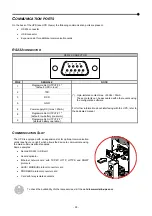
Page 29: ...he dedicated manual 2 TXD 3 RXD 5 GND 6 Power supply DC Imax 20mA 8 Programmable OUTPUT 1 default low battery pre alarm 9 Programmable OUTPUT 2 default battery operation COMMUNICATION SLOT The UPS is equipped with an expansion slot for optional communication cards see figure on right which allows the device to communicate using the main communication standards Some examples Second RS232 USB port S...

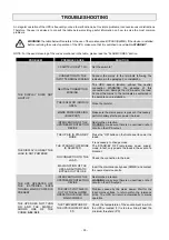
Page 30: ... necessary perform battery start up to power the load INTERVENTION OF THE UPSTREAM PROTECTION DEVICE Restore the protection WARNING make sure there is no overload or short circuit on the UPS output THE DISPLAY IS ON BUT THE LOAD IS NOT POWERED THE UPS IS IN STAND BY MODE Press the ON button on the front panel to power the loads THE STAND BY OFF MODE IS SELECTED It is necessary to change mode The S...

Page 31: ...ain if the problem occurs again call the support centre THE BUZZER SOUNDS CONTINUOUSLY AND THE DISPLAY SHOWS ONE OF THE CODES F04 L04 THE TEMPERATURE OF THE DISSIPATORS INSIDE THE UPS IS TOO HIGH Check that the temperature of the environment in which the UPS is located does not exceed 40 C THE BUZZER SOUNDS CONTINUOUSLY AND THE DISPLAY SHOWS ONE OF THE CODES F53 L53 THERE IS A FAULT ON ONE OR MORE...

Page 32: ...issing or not connected A63 Waiting for battery charging Allarmi these are more critical problems than anomalies because if they persist they could cause the UPS to lock in a very short time CODE DESCRIPTION F03 Incorrect auxiliary power supply F04 Dissipator overtemperature F05 Temperature sensor1 faulty F07 Temperature sensor2 faulty F11 Input relay faulty F13 Capacitor pre charge failed F21 Cap...

Page 33: ...liary power supply L04 Dissipator over temperature L05 Temperature sensor1 faulty L07 Temperature sensor2 faulty Inverter circuit faulty L10 Input fuse broken or input relay stuck does not close L11 Input relay faulty L13 Capacitor pre charge failed L20 Capacitor bank undervoltage L21 Capacitor bank overvoltage L40 Inverter overvoltage L41 Continuous output voltage L42 Incorrect inverter voltage L...

Page 34: ...5 secs OTHER Leakage current to earth mA 1 5 Ambient temperature 4 C 0 40 Humidity 90 senza condensa Protection devices excessively low batteries overcurrent short circuit overvoltage undervoltage circuit breaker Dimensions W x D x H mm 131 x 640 x 448 Tower 19 x 640 x 3U Rack Weight Kg 40 For more details please consult the web site 1 nominal load nominal voltage of 220 Vac battery charging 2 To ...

Page 35: ......

Page 36: ...0MNSDU4K0RUENUA ...

Reviews: