10
b
See the instruction manual provided with the burner for further information on burner installation, electrical con-
nections, burner adjustments.
If a two stage burner is installed, 1st stage heat input must not be less than 70% of total heat input.
A
ø
L
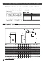
IMPORTANT
If you are installing a new boiler but re-using an old bur-
ner, always perform the following checks.
- Make sure that the performance of the old burner is
adequate for the requirements of the boiler.
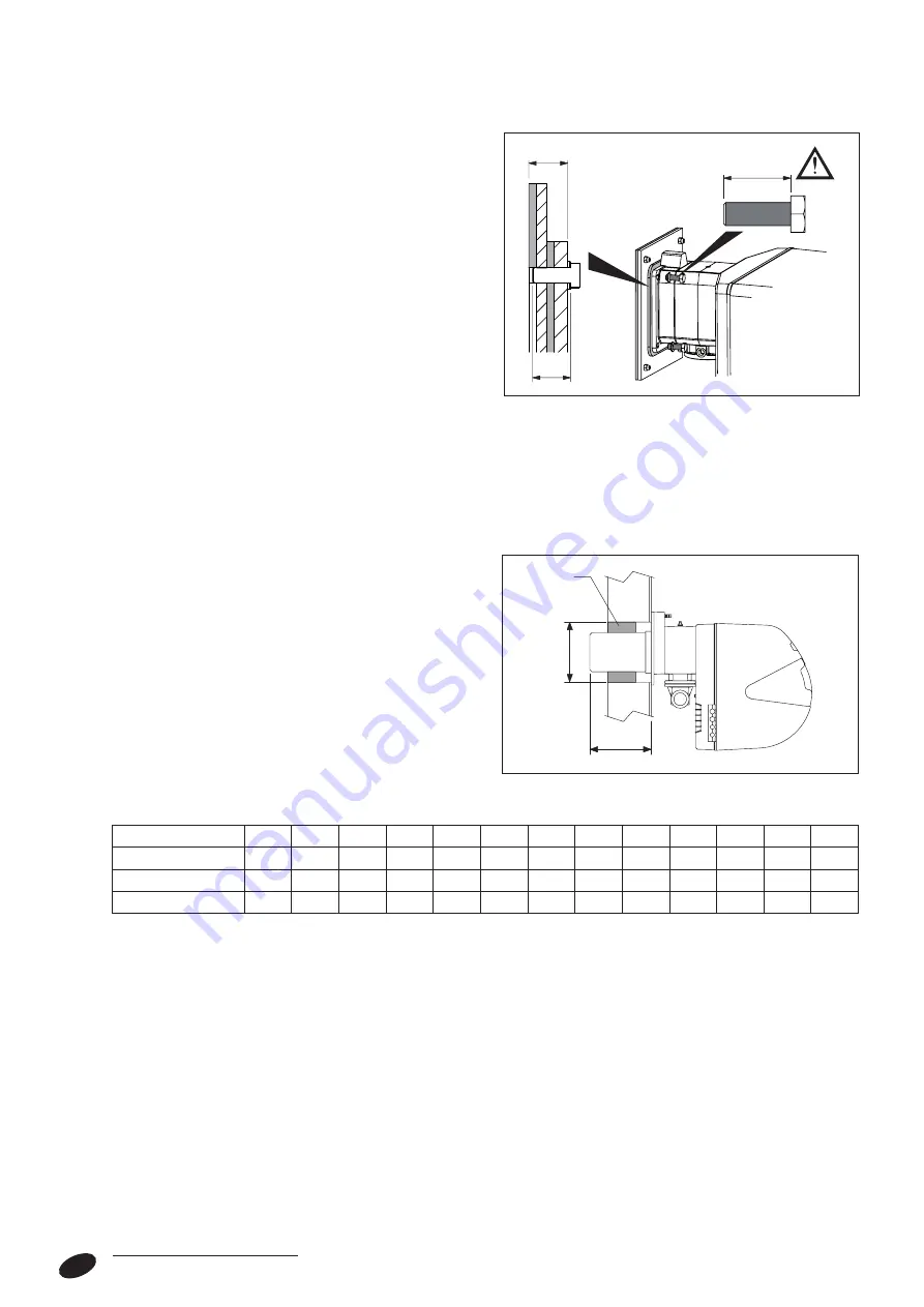
- Make sure that the length and diameter of the burner’s
blast tube are as specified in the following table.
b
When you finish installing the burner in the boiler,
fill the gap between the burner’s blast tube and
the refractory material in the door with the ceramic
insulation (A) supplied with the boiler.
a
Do not re-use old burners if their blast tube lengths are below those specified in the table.
RTS 3S
90
115
166
217
255
349
448
511
639
850
1160
1450
L min
128
128
128
128
155
155
195
195
200
200
205
205
mm
Diameter of door hole
140
140
162
162
180
180
205
205
205
230
230
270
Ø mm
Thickness of door
93
93
93
93
103
103
118
118
119
119
119
119
mm
L < S
S
L
IMPORTANT NOTES FOR BURNER
INSTALLATION
Before fixing the burner to the boiler, make sure that:
- The door opens the right way (see the relevant sec-
tions for details on how to reverse the door).
- The length (L) of the burner fixing bolts is less than
(S), i.e. the total depth of the seal, plates and washer.
Longer bolts can cause the door to warp, compro-
mising its ability to seal the boiler hermetically and
permitting the release of combustion fumes.
To ensure correct burner installation, also refer to the
burner’s own manual.
GENERAL


