22
INSTALLER
r
RTS 3S
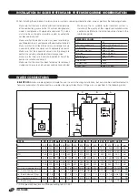
boilers are designed and made for use in central heating installations, but can also be used for domestic
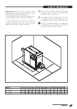
hot water production if connected to a suitable storage cylinder. Water fittings are as specified in the following table:
When installing these boilers in old systems or systems requiring modernisation, always perform the following checks:
- Make sure that the stack is able to withstand the temperature
of the combustion gases and that it has been designed and
made in compliance with applicable standards. The stack
must also be as straight as possible, sealed, insulated and
not blocked or choked
- Make sure that the electrical system has been installed by a
qualified electrician in compliance with applicable standards
- Make sure that the oil feed line and any oil storage tank are
made and installed in compliance with applicable standards
- Make sure that the expansion vessels are big enough to
contain the volume generated by thermal expansion
- Make sure that flow rate, head and direction of flow of the
pumps are suitable and correct
- Make sure that the circuit has been flushed out to remove all
sludge and lime scale, and has been vented and seal tested
- Make sure that a suitable water treatment system is
installed if the quality of the supply/recirculation water
so demands (Refer to the reference values listed in the
table alongside).
REFERENCE VALUES
PH
6-8
Electrical conductivity
below 200
μS/cm (25°C)
Chlorine ions
below 50 ppm
Sulphuric acid ions
below 50 ppm
Total iron
below 0,3 ppm
Alkalinity M
below 50 ppm
Total hardness
35° F
Sulphur ions
none
Ammonia ions
none
Silicon ions
below 30 ppm
A
B
C
SC
S
Ø D
E
F
MI
AS
RI
G
RTS 3S
90
115 166 217 255 349 448 511
639
850
1160 1450
A
320
335
348
348
360
390
395
395
450
512
514
563
mm
B
530
650
800
800
890 1085 1200 1200
1400
1570
1865
2030
mm
C
305
345
352
352
410
485
490
490
525
575
575
580
mm
Ø D
180
200
250
250
250
250
300
300
350
350
400
450
mm
E
870
946 1005 1005 1130 1130 1290 1290
1405
1445
1580
1695
mm
F
175
150
148
148
187
187
185
185
205
190
218
190
mm
G
130
200
200
200
200
300
250
250
300
350
350
700
mm
Mi - Central heating flow (*)
2”
2”
2”1/2 2”1/2 2”1/2 DN80 DN80 DN80 DN100 DN125 DN125 DN150 G” /DN
Ri - Central heating return (*)
2”
2”
2”1/2 2”1/2 2”1/2 DN80 DN80 DN80 DN100 DN125 DN125 DN150 G” /DN
As - Safety device fitting
1”1/4 1”1/4 1”1/4 1”1/4 1”1/4 1”1/4 1”1/2 1”1/2 1”1/2
2”1/2
2”1/2
DN80 G” /DN
Sc - Condensate drain
3/4”
3/4”
3/4”
3/4”
3/4”
3/4”
3/4”
3/4”
3/4”
1”
1”
1”
G” /DN
S - Boiler drain
3/4”
1”
1”
1”
1”
1”
1”1/4 1”1/4 1”1/4
1”1/4
1”1/4
1”1/4 G” /DN
(*) All flanged connections are PN6 according to EN 1092-1.
Water connections
WATER CONNECTIONS
Installation in older systems and systems requiring modernisation
INSTALLATION IN OLDER SYSTEMS AND SYSTEMS REQUIRING MODERNISATION


