background image

26

SYSTEM MANAGER

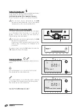
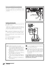
If you are going to be away for a short period of time like 
a weekend or a short holiday, etc. proceed as follows.

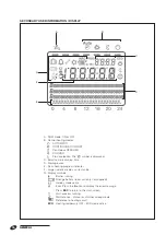
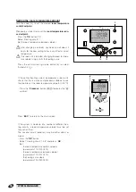
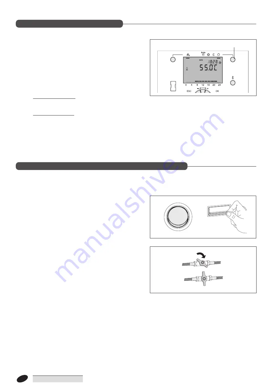
- Press the central heating mode button (5) to select 

"Protection" mode (

b

).

Power to the boiler remains switched on, and the display 
remains active. The fuel feed also remains open so that 
the 

frost protection

 function can protect the boiler 

against freezing.
Boiler frost protection: if boiler temperature falls below 
5°C, the burner starts up at full power until boiler tempe-
rature reaches 40°C.
Plant frost protection: This function is only active if an 
outside temperature sensor is connected.
If outside temperature drops below -4°C the pumps are 
switched on. If outside temperature is between -5° and 
1.5°C, the pumps are switched on for 10 minutes at inter-
vals of 6 hours. If outside temperature is above 1.5°C the 
pumps are switched off.

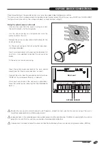
If the boiler is not going to be used for an extended period 

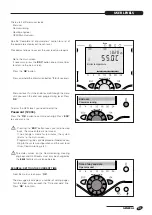
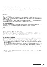
of time, proceed as follows to prepare it for shut-down.

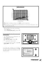
-  Turn the control panel power switch OFF and make sure 

that the display goes out.

- Turn the mains power switch OFF.

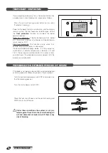
- Close the fuel shut off cock and the central heating and 

DHW circuit shut off cocks.

Under these conditions the system is not pro-

tected against frost . Drain the central heating cir-

cuit and domestic hot water circuit if there is any 

risk of freezing .

ON 

OFF 

5

Boiler temperature

Preparing for extended periods of disuse

PREPARING FOR EXTENDED PERIODS OF DISUSE

Temporary shutdown

TEMPORARY SHUTDOWN

Summary of Contents for 20035952

Page 1: ...1 INSTALLATION MAINTENANCE AND SYSTEM MANAGEMENT MANUAL CONDENSING BOILERS TAU UNIT OIL 35 B OIL 55 B ...

Page 2: ...owing directives Efficiency Directive 92 42 EEC HHHH Electromagnetic Compatibility Directive 2004 108 CE Ecodesign Directive 2009 125 CE for energy related products Energy Labelling Directive 2010 30 EU Low Voltage Directive 2006 95 CE Delegated Regulation EU N 811 2013 Delegated Regulation EU N 813 2013 CONFORMITY RANGE ...

Page 3: ...ervice and to provide comfort in the home for many years to come This manual provides information that is essential to the installation of the appliance Used in conjunction with your own knowledge and expertise it will enable you to install the appliance quickly easily and correctly Once again please accept our thanks and our congratulations on your choice of product Riello S p a ...

Page 4: ...n 26 Preparing for extended periods of disuse 26 Cleaning 27 Maintenance 27 Useful information 28 INSTALLER 29 Unpacking the product 29 Dimensions and weight 29 Handling 30 Place of installation 31 Installation in older systems and systems requiring modernisation 31 Heating circuit water 31 Water connections 34 Draining the condensate 36 Electrical connections 36 Outside sensor connections 39 Fuel...

Page 5: ...ct the r reseller from whom you purchased the product if you notice any problems bThis TAU UNIT OIL r boiler must be installed by a legally qualified heating engineer On completion of the installation the heating engineer must issue the owner with a declaration of conformity confir ming that the installation has been completed to the highest standards in compliance with the instruc tions provided ...

Page 6: ...ional zone to be served directly and also permits integration with r solar heating systems without additional controllers TAU UNIT OIL r boilers are equipped with the following safety devices A safety valve that opens if pressure in the heating circuit rises above the 3 bar threshold A safety thermostat that forces the boiler to perform a safety shutdown if temperature exceeds the safety threshold...

Page 7: ...N IT FR CH BE B23 B23P C13 C33 C63 230 50 GASOLIO FIOUL HEIZÍL European Directive 92 42 EEC Pms bar T C C Qn min Pn min TIPO TYP TYP COMBUSTIBILE COMBUSTIBLE BRENNSTOFF BRANDSTOF Qn max Pn max Mod Cod N kW kW kW kW IP W V Hz RIELLO S p A Via Ing Pilade Riello 7 37045 Legnago VR ITALY Mod Cod N Qn max kW Pn max kW bar Pms RIELLO S p A Via Ing Pilade Riello 7 37045 Legnago VR ITALY PAESE DI DESTINAZ...

Page 8: ...changer 5 Condensate drain siphon 6 Inspection panel 7 Automatic vent valve 8 Safety valve 3 bar 9 Boiler sensor sockets 10 Boiler body 11 Flame inspection window 12 Burner bracket 13 Burner 14 Control panel 15 Pressure gauge 16 Comburent air inlet pipe 17 Boiler drain cock 18 Lifting eyebolts 19 Socket for flue gas thermostat 20 Flue gas exhaust 21 Boiler body insulation Design DESIGN ...

Page 9: ... vent valve 5 Safety valve 3 bar 6 Pressure gauge 7 Secondary heat exchanger 8 Condensate drain siphon 9 Inspection panel 10 Boiler sensor sockets 11 Burner bracket 12 Burner 13 Control panel 14 Boiler body 15 Comburent air inlet pipe 16 Flame inspection window 17 Boiler drain cock 18 Socket for flue gas thermostat 19 Flue gas exhaust 20 Lifting eyebolts 21 Boiler body insulation ...

Page 10: ... Annual energy consumption QHE 107 169 GJ Noise level sound power LWA 70 71 dB A Emissions at maximum heat input NOx referred to HCV 94 96 mg kWh Smoke scale 0 5 CO2 12 5 CO w a 23 ppm Flue gas temperature Δt 80 60 C 70 67 Δt 50 30 C 44 46 Flue gas mass flow rate 0 013 0 023 Kg s Flue gas thermostat trip temperature 90 C Water side pressure drop Δt 20 C 50 75 mbar Maximum working pressure 3 bar Sa...

Page 11: ...n siphon 9 Drains 10 Flue gas exhaust MI CH flow RI CH return ACCESSORY CODE TAU UNIT OIL 35 B TAU UNIT OIL 55 B Mixed zone kit 20039723 Second mixed zone electrical kit 20011194 20102310 Flue kit 80 125 20012802 20012802 Sealing kit 80 80 20012807 20012807 Solar collector sensor kit 4031913 4031913 Storage cylinder temperature sensor kit 4031847 4031847 Remote control RC2 4334410 4334410 Accessor...

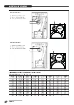
Page 12: ...05 110 0 508 170 0 117 5 0 42158 55 0 2989 115 0 443 175 0 105 0 0 32555 60 0 2490 120 0 387 180 0 95 5 0 25339 65 0 2084 125 0 339 185 0 85 10 0 19873 70 0 1753 130 0 298 190 0 77 15 0 15699 75 0 1481 135 0 262 195 0 70 20 0 12488 80 0 1256 140 0 232 200 0 64 25 0 10000 85 0 1070 145 0 206 TAU UNIT OIL 35 B 1 Boiler temperature sensor 2 Safety thermostat sensor 3 Flue gas thermostat sensor TAU UN...

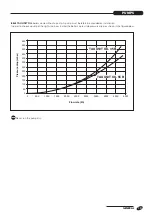
Page 13: ...rder to choose a pump of the right size bear in mind the boiler s water side pressure drop as shown in the figure below PRESSURE DROP mbar FLOW RATE l h 0 0 2000 2500 3000 3500 4000 4500 5000 1500 1000 500 50 100 150 200 250 300 350 400 450 500 600 550 TAU UNIT OIL 35 B TAU UNIT OIL 55 B Pressure drop mbar Flow rate l h Pumps PUMPS ...

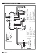
Page 14: ... cylinder phase 1st stage CH 1 snsr ground Boiler snsr DHW 1 snsr Out temp snsr ground ground ground QX1 IMF Multifunctional input FU Fuse 6 3 A T IP Main switch SCH1 Main board SCH2 Display and control card TF Flue gas thermostat 90 C TS Safety thermostat 110 C 0 6 H1 Safety thermostat or flue gas thermostat trip indicator H2 Burner lockout indicator AP Burner controller RS Remote burner reset QX...

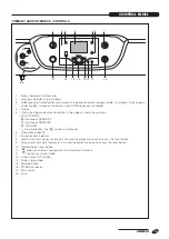
Page 15: ...mbols s AUTOMATIC o Continuous COMFORT l Continuous REDUCED F COOLING b Frost protection The t symbol is displayed 6 Information button i 7 Burner lockout indicator 8 Manual reset for flue gas thermostat Unscrew the protective cover to access the reset button 9 Manual reset for safety thermostat Unscrew the protective cover to access the reset button 10 Remote burner reset button 11 p button for c...

Page 16: ...ily heating program indicator F Large numeric display current value G Display symbols f Burner running B Change battery room unit only not supplied w Holiday mode active n Error Press the i button to display the error message Press ESC to return to the main screen C Wait process running h Maintenance manual or chimney sweep mode Reference to heating circuit ECO Heating temporarily OFF ECO mode act...

Page 17: ...l remote storage cylinder is installed and domestic hot water is drawn off while the central heating circuit is also in use this function directs boiler power mainly to the DHW circuit Boiler switching differential This establishes a mini mum run time for the burner to stop it igniting and shutting down repeatedly The burner shuts down only if boiler temperature exceeds a predetermined threshold p...

Page 18: ...tion o or l In continuous mode room temperature is controlled on the basis of the comfort reduced setting o Central heating set to comfort setpoint l Central heating set to economy setpoint Characteristics Central heating is continuously on with no time program All protection functions are active Summer winter switching is automatic ECO functions and 24h limit functions are inactive if comfort lev...

Page 19: ...the chimney sweep button 11 briefly max 3 seconds The h symbol is displayed Chimney sweep mode prepares the boiler for combustion analysis To exit chimney sweep mode press the button 11 again The system exits chimney sweep mode automatically after 1 hour 12 11 6 Boiler temperature Room temperature Minimum room temperature Maximum room temperature Room 1 setpoint Room 2 setpoint Room 3 setpoint Cas...

Page 20: ...der certain con ditions n This symbol appears if a system error has occurred Press button 6 for further information h This symbol appears if a maintenance alarm is present or if the boiler has entered a special functioning mode Press button 6 for further information See also Error Maintenance codes Error 30 Flow sensor 1 Attention 3 Maintenance interval exceeded 6 6 Error 30 Flow sensor 1 Attentio...

Page 21: ...e Password 12434 Press the OK button to confirm each digit Press ESC to cancel an entry b Pressing the ESC button takes you just one step back the value entered is not saved If no change is made for 8 minutes the system returns to the main screen Programming lines are displayed or hidden accor ding to the system configuration and the user level User Commissioning etc b Parameter values on the Comm...

Page 22: ...s stage you can continue programming or press the central heating mode button 5 to return to the main screen EXAMPLE OF THE MENU STRUCTURE Hours minutes Time of day and date Ore minuti Ora e data Ore minuti Ora e data Ore minuti Ora e data Ore minuti Ora e data Ore minuti Ora e data 5 Time of day and date Heating engineer level parameters Hours minutes Hours 1 24 h Operator unit Month day Minutes ...

Page 23: ... bar but below the maximum limit specified for the boiler If water pressure is low contact r s Technical Assistance Service Switch the electricity supply ON at the system s main switch and at the control panel Check that the display comes on When the boiler is first powered on it performs a num ber of self tests These may take a few minutes When the tests are completed the display reads out boiler...

Page 24: ...n 5 to select Automatic b If the central heating system incorporates a room unit check that this is active and proceed as follows to use the knob to set the room temperature setpoint 20 C Press the Presence button o l to display the o symbol Press ESC to return to the main screen If the system is made up of a number of different hea ting circuits a room temperature setpoint must be set for each of...

Page 25: ... Error 30 CH flow 1 sensor If any boiler ignition or operating errors are detected the n symbol appears on the display Press the Info i button to display the type of error See also Error Maintenance codes Only for 28 120 B models with a remote storage cylinder optional Press the v button to turn on DHW production A line appears under the DHW symbol Press the OK button Select Domestic hot water and...

Page 26: ...ps below 4 C the pumps are switched on If outside temperature is between 5 and 1 5 C the pumps are switched on for 10 minutes at inter vals of 6 hours If outside temperature is above 1 5 C the pumps are switched off If the boiler is not going to be used for an extended period of time proceed as follows to prepare it for shut down Turn the control panel power switch OFF and make sure that the displ...

Page 27: ...neer aDo not use abrasive products petrol or triethylene aNever clean or service the boiler without first disconnecting it from the mains electricity supply by turning the main power switch OFF Please remember that THE PERSON RESPONSIBLE FOR SYSTEM MANAGEMENT MUST ENSURE THAT PROFESSIONALLY QUALIFIED PERSONNEL UNDERTAKE PERIODIC MAINTENANCE AND COMBUSTION EFFICIENCY MEASUREMENTS r s Technical Assi...

Page 28: ...chnical Assistance Service Mr Address Tel Fuel oil supplier Mr Address Tel Installer Mr Address Tel Date Work done Date Quantity supplied Date Quantity supplied Date Quantity supplied Date Quantity supplied Useful information USEFUL INFORMATION ...

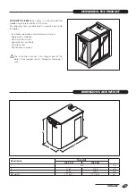
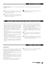
Page 29: ...re parts catalogue Certificate of warranty Hydraulic test certificate Outside sensor Connections and hose bThe instruction manual is an integral part of the boiler Once located read it thoroughly and keep it safe P H L Description TAU UNIT OIL 35 B OIL 55 B L 600 mm P 1150 1150 mm H 1025 1025 mm Net weight 171 2 217 2 kg Dimensions and weight DIMENSIONS AND WEIGHT Unpacking the product UNPACKING T...

Page 30: ...sing the eyebolts 4 inside the unit bWear suitable personal protective equipment and use suitable safety devices bRemove the protective film F from the boiler s front panel and control panel bTo level the boiler use the hexagonal head screws accessible though the slots V on either side of the boi ler two screws per side aDo not leave packaging material within the reach of children since it can bec...

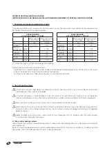
Page 31: ...lushed out to remove all sludge and lime scale and that it has been bled and seal tested Make sure that a suitable water treatment system is in stalled See the Water in central heating systems sec tion Refer to the r catalogue for details of specific products bThe manufacturer declines all responsibility for da mage caused by incorrectly constructed flue sy stems bFlue pipes for condensing boilers...

Page 32: ...phides mg l 10 Nitrides mg l 10 Iron mg l 0 5 2 Central heating systems b Do not use automatic filling devices to add water to central heating systems Use a manual device instead and record top ups in the system service book b If a system comprises a number of boilers when that system is first put into service make sure that all the boilers function simultaneously or on a short interval rotation b...

Page 33: ...central heating systems If oxygen enters a circuit continuously or even intermittently e g in under floor heating systems whose pipes are not protected by impermeable synthetic sheaths in circuits with open expansion vessels or in circuits that require frequent top ups always separate the boiler s water circuit from the central heating circuit Mistakes to avoid and precautions From what has been s...

Page 34: ...ponsibility for damage caused by water escaping from the safety valve bCircuits filled with anti freeze must be fitted with water disconnectors bLow temperature under floor heating systems must be fed through a circuit fitted with a mixer valve bThe choice of system components and the method of their installation are left up to the heating engi neer installing the system Installers must use their ...

Page 35: ...mp PR 5890 DHW recirculation pump Q4 DHW recirculation parameters 5730 sensor 5930 B39 Direct CH circuit pump PD 5890 CH pump CRP Q20 Expansion kit 20011194 20102310 must be installed before all three functions can be available together 16 Non return valve 17 Thermostatic mixer valve 18 r 7200 2 solar storage cylinder 19 DHW recirculation sensor 20 CH pump 21 CH manifolds 22 Mixer valve UAC Domest...

Page 36: ...condensate neutralisation units deemed neces sary may be connected downstream from the siphon Evaluate the neutralisation unit after one year of opera tion to estimate the duration of the neutralisation char ge The total duration of the charge can be estimated from the level after one year bIt is mandatory to use a condensate trap see the r catalogue i i 3 BOILER Drain Condensate from stack Conden...

Page 37: ...vant section Connecting up the room unit not supplied Use a two core cable to connect the room unit to termi nals CL and CL on the main board taking care not to invert polarity Set the relevant parameters to assign the room unit to the corresponding circuit see Preparing for initial start up Once you have made all the necessary connections close the control panel reversing the steps followed to op...

Page 38: ...uel and or water pipes to ground the appliance aDo not route the power cable or room thermostat cables near hot surfaces like heating circuit flow pipes Use a suitable class of cable if there is any possibility of contact with parts at temperatu res above 50 C The manufacturer declines all responsibility for damage caused by failing to ground the appliance adequately or by failure to respect the w...

Page 39: ... using the two expan sion plugs provided Insert a two core cable with cross section between 0 5 and 1mm2 not supplied to connect the sensor to the boiler Fit the cover on the sensor casing Open the control panel and identify the main control board see the Electrical connections section Connect the wires from the outside sensor to terminals M B9 on the main board Polarity is irrelevant Once you hav...

Page 40: ...4 0 9 369 3 0 3 279 18 0 1 320 39 0 595 23 0 8 880 2 0 3 131 19 0 1 268 40 0 575 22 0 8 420 1 0 2 990 20 0 1 218 41 0 555 21 0 7 986 0 0 2 857 21 0 1 170 42 0 536 20 0 7 578 1 0 2 730 22 0 1 125 43 0 517 19 0 7 193 2 0 2 610 23 0 1 081 44 0 500 18 0 6 831 3 0 2 496 24 0 1 040 45 0 483 17 0 6 489 4 0 2 387 25 0 1 000 46 0 466 16 0 6 166 5 0 2 284 26 0 962 47 0 451 15 0 5 861 6 0 2 186 27 0 926 48 0...

Page 41: ...in the fuel oil feed never exceeds 0 4 bar 30 cm Hg Over this value the fuel oil will release gas Make sure that the fuel oil hoses are perfectly oil tight bClean out the fuel oil tank at suitable intervals bThe fuel oil feed line must be suitable for the flow rate demanded by the burner The fuel oil feed system must also be equipped with all the necessa ry safety and control devices required by a...

Page 42: ...irectly from the room where the boiler is installed Flue gas vent via horizontal or vertical flues with air ventilation to room B23P As B23 but with flue gas vent designed to operate at positive pressure C13 Concentric wall vent Twin flue pipes can also be used but the wall through pipes must be concentric or located close enough to be subjected to similar wind conditions C33 Concentric roof vent ...

Page 43: ...must be made from condensate acid resistant materials r TAU UNIT OIL boilers can also be installed in B23 open configurations using suitable piping in compliance with applicable laws and standards bEven if the flue pipes pass through combustible walls it is not necessary to respect a minimum installation distance between the flue and the walls since flue gas temperature is below the maximum permit...

Page 44: ...ng the system Open any non return valves in the CH circuit to facilitate filling Slacken off the cap of the automatic vent valve 2 to let air out of the system Open the central heating circuit shut off cocks and slowly fill the system until the pressure gauge 3 reads out value of 1 5 bar cold Close the shut off cocks and tighten down the cap on the automatic vent valve 2 Close the CH circuit s non...

Page 45: ...perly pre charged The cap on the vent valve 2 must be open All electrical connections to the mains supply and to the system s control and safety devices must have been made correctly The flue gas exhaust and flue pipes must have been correctly installed and connected The pump s fitted on installation must turn freely Unscrew the inspection cap and use a flat blade screwdriver to check that the pum...

Page 46: ...ct Language and press OK Set the language you want SEE THE INSTALLER PARAMETERS MANUAL TO ACCESSTHE HEATING ENGINEER INSTALLER FUN CTIONING LEVEL ON OFF Boiler temperature Time of day and date Operator unit Commissioning Heating Only for 20 28 models with a remote storage cylinder optional If a storage cylinder with temperature sensor is con nected install the Storage cylinder sensor kit code 4031...

Page 47: ... in the right direction Turn the main power switch OFF and make sure that the boiler shuts down completely Provided these conditions are satisfied re start the boiler press the chimney sweep button p briefly max 3 se conds and perform combustion analysis Press the p button again to exit chimney sweep mode b The flue should be fitted with a test socket for com bustion analysis Temperatura caldaia O...

Page 48: ...utside temperature drops below 4 C the pumps are switched on If outside temperature is between 5 and 1 5 C the pumps are switched on for 10 minutes at inter vals of 6 hours If outside temperature is above 1 5 C the pumps are switched off If the boiler is not going to be used for an extended period of time proceed as follows to prepare it for shut down Turn the control panel power switch OFF and ma...

Page 49: ...the following operations before beginning any maintenance Switch the electricity supply OFF at the system s main switch and at the control panel Close the fuel shut off cocks Once all the necessary maintenance has been completed restore all original settings see the values in the tables below Calibration table for STANDARD NOZZLE Description TAU UNIT OIL 35 B OIL 55 B Air damper position 4 5 line ...

Page 50: ...l pump 2 Control box 3 Reset button with lock out signal 4 Flange with insulating gasket 5 Air damper adjustment screw 6 Air intake 7 Pump pressure adjustment screw 8 Pressure gauge connection 9 Flame sensor 10 Flame pipe 11 Capacitor 12 Motor 13 Heater Oil burner OIL BURNER ...

Page 51: ...the connector 2 from the burner controller Disconnect the air inlet pipe 3 Unscrew the fixing screws 7 and remove the cover 8 from the burner body Unscrew the fixing nut 4 and remove the burner Pull the burner 6 out taking care not to damage it Turn the burner upright Fix the burner to the bracket 9 by engaging the pin B in the hole A 2 3 1 5 6 4 7 7 7 8 A B 9 ...

Page 52: ...ct the hoses 5 first Use a suita ble rag to soak up the fuel that inevitably comes out 0 5 5 0 5 X SETTING THE ELECTRODES bThe position of the electrodes and combustion head is not adjustable If ignition problems are encountered make sure that the dimensions shown in the figure are respected Model X TAU UNIT OIL 35 B 63 TAU UNIT OIL 55 B 88 ...

Page 53: ...ary pressure measurement fitting ADJUSTING PUMP PRESSURE Turn the adjuster screw 5 to achieve the pressure setting specified in the table on page 49 ADJUSTING THE AIR DAMPER The air damper can be adjusted without removing the burner cover Use an Allen key to turn the adjuster screw 1 to achie ve the required setting on the graduated scale 2 bSee the table on page 49 5 1 2 3 4 5 0 6 1 2 ...

Page 54: ...om the electrodes The burner must be shut down and power and fuel disconnected before the control box is removed BURNER ELECTRICAL CONNECTIONS L1 N T1 T2 S3 B4 1 2 L1 N T1 T2 S3 B4 R E S E T MO535 MRSFUI Burner ground CONTROL BOX Capacitor Motor Heating element Black White Blue Flame detector Burner lockout indicator on boiler control panel 7 pin connector 2 pin connector Fuel shut off cock Remote...

Page 55: ...reaction time control box remains in waiting mode for t1 1 sec t2 Initialisation time for checking time period after main power start up 3 5 sec t2l Checks for presence of extraneous light or parasite flame during t2 waiting mode for t2l then lockout the motor does not start 25 sec t2p Light oil pre heating time waiting state for t2p then lockout max 600 t3 Pre purging time the fan motor is runnin...

Page 56: ...on time control box remains in waiting mode for t1 1 sec t2 Initialisation time for checking time period af ter main power start up 3 5 sec t2l Checks for presence of extraneous light or parasite flame during t2 waiting mode for t2l then lockout the motor does not start 25 sec t2p Light oil pre heating time waiting state for t2p then lockout max 600 t3 Pre purging time the fan motor is running the...

Page 57: ...nomaly Green Red flashing Fast 0 2 0 2 Lockout for no flame after Ts Red Lockout for extraneous light signal or for parasite flame Red flashing Slow 0 5 0 5 Lockout for maximum number of cycle repetitions lack of flame during operation Red flashing Fast 0 2 0 2 Lockout for max pre heating time exceeded Red flashing Slow 0 5 2 5 Lockout for fan motor error Red Orange flashing Reversed 2 5 0 5 Locko...

Page 58: ...empt Disconnect and reconnect power to the burner to obtain a further complete series of startup attempts max 3 for the next heat request PRESENCE OF EXTRANEOUS LIGHT OR PARASITE FLAME The presence of a parasite flame or extraneous light can be detected in the stand by state when the burner is stopped or waiting for a heat request or during pre heating If the presence of a flame or extraneous ligh...

Page 59: ... and goes into lockout The fault is not detected during normal operation the burner remains in this state The fault is not detected if the burner is in lockout INTERNAL VOLTAGE ERROR The burner controller automatically checks that internal voltage is correct An error is indicated by the LED flashing If the fault is detected during the initialisation the burner does not start If an error is detecte...

Page 60: ...are present Permit de activation of pre heating only from the remote reset button Switch on the burner and simultaneously hold down the remote reset button for 3 seconds RED Release the remote reset button within 3 seconds OFF The burner will start de activation of pre heating only if the remote reset button is released within 3 seconds Pre heating remains de activated until a lockout occurs mains...

Page 61: ...RESTART Function Button re lease time No of blinks of the LED for menu page No of times the reset button is pressed No of blinks of the LED green Quitting the menu Switching off test 5s t 10s 2 blinks RED none none Automatic starting at the end of the blinking Post purging 10s t 15s 1 blink GREEN 1 10 sec 2 20 sec 3 30 sec 4 60 sec default 5 120 sec 6 0 sec disabled 1 blink 2 blinks 3 blinks 4 bli...

Page 62: ...ec GREEN led blinking 3 times Release the button GREEN led OFF Press the button 1 time to disable the function Press the button 2 times to enable a shut down every hour Press the button 3 times to enable a shut down every hour 24 hours GREEN led ON and OFF at each pressure and release After 10 sec the GREEN LED will blink for the number of times programmed 0 5 sec ON 0 5 sec OFF The modification o...

Page 63: ...er locks out before or during pre purg ing or pre heat ing The flame detector is reading extraneous light Red flashing Eliminate the light source The burner performs pre ventilation and ignition cor rectly but enters lockout after about 5 seconds The flame detector is dirty Red Clean the flame detector The flame detector is faulty Replace as necessary The flame detaches or fails Check fuel oil pre...

Page 64: ... INTERNAL CLEANING Close the fuel shut off cocks before removing any part of the boiler bTo ensure that the boiler remains efficient change the burner nozzle and check the smoke scale reading at every annual maintenance Also check combustion conditions at regular intervals during normal functioning Removing the casing panels Remove the front panel 1 and side panel 2 Remove the top panel 3 Removing...

Page 65: ...mbustion chamber Take care not to damage the flame guard 13 b Do not use chemical solvents or detergents to clean the heat exchanger Proceed as follows on completion of cleaning Refit the turbulators 12 in the flue gas pipes making sure that they are correctly seated Check the condition of the flame guard 13 and seal 14 Replace as necessary On completion of cleaning follow the above steps in the r...

Page 66: ...the turbulators 3 and check them for wear Replace as necessary Use a flue brush or other suitable tool to clean inside the flue gas pipes Remove the condensate drain hose 4 and the siphon 5 Remove the flue gas temperature sensor 6 Unscrew the nuts 7 and remove the bottom cover 8 Clean out any soot Proceed as follows on completion of cleaning Refit the turbulators 3 in the flue gas pipes making sur...

Page 67: ...exchanger dirty Clean the combustion chamber Insufficient air fuel flow to burner Check and adjust the burner Boiler control setpoint incorrect Check the correct setting The boiler does not reach its temperature setpoint Boiler control setpoint incorrect Check the temperature setting Check the electrical wiring Check the positioning of sensors No water supply Check the vent valve Check the circuit...

Page 68: ...torage cylinder Check functioning of DHW circuit pump Check settings of control thermostats Check the positioning of sensors Check boiler operating temperature Reduced supply of domestic hot water Pump seized Bad electrical connections Check the pump and the connections No heat request from boiler controller Check controller sensors and connections The central heating or DHW pump is not working Ch...

Page 69: ...GENERAL 69 ...

Page 70: ...GENERAL 70 ...

Page 71: ...GENERAL 71 ...

Page 72: ...Tel 0442630111 Fax 0442630371 www riello it As part of the company s ongoing commitment to perfecting its range of products the appearance dimensions technical data equipment and accessories may be subject to variation Cod 20091420 ...

Reviews: