INSTALLER
37
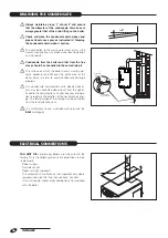
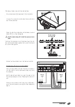
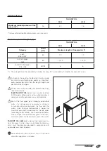
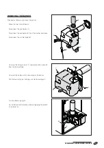
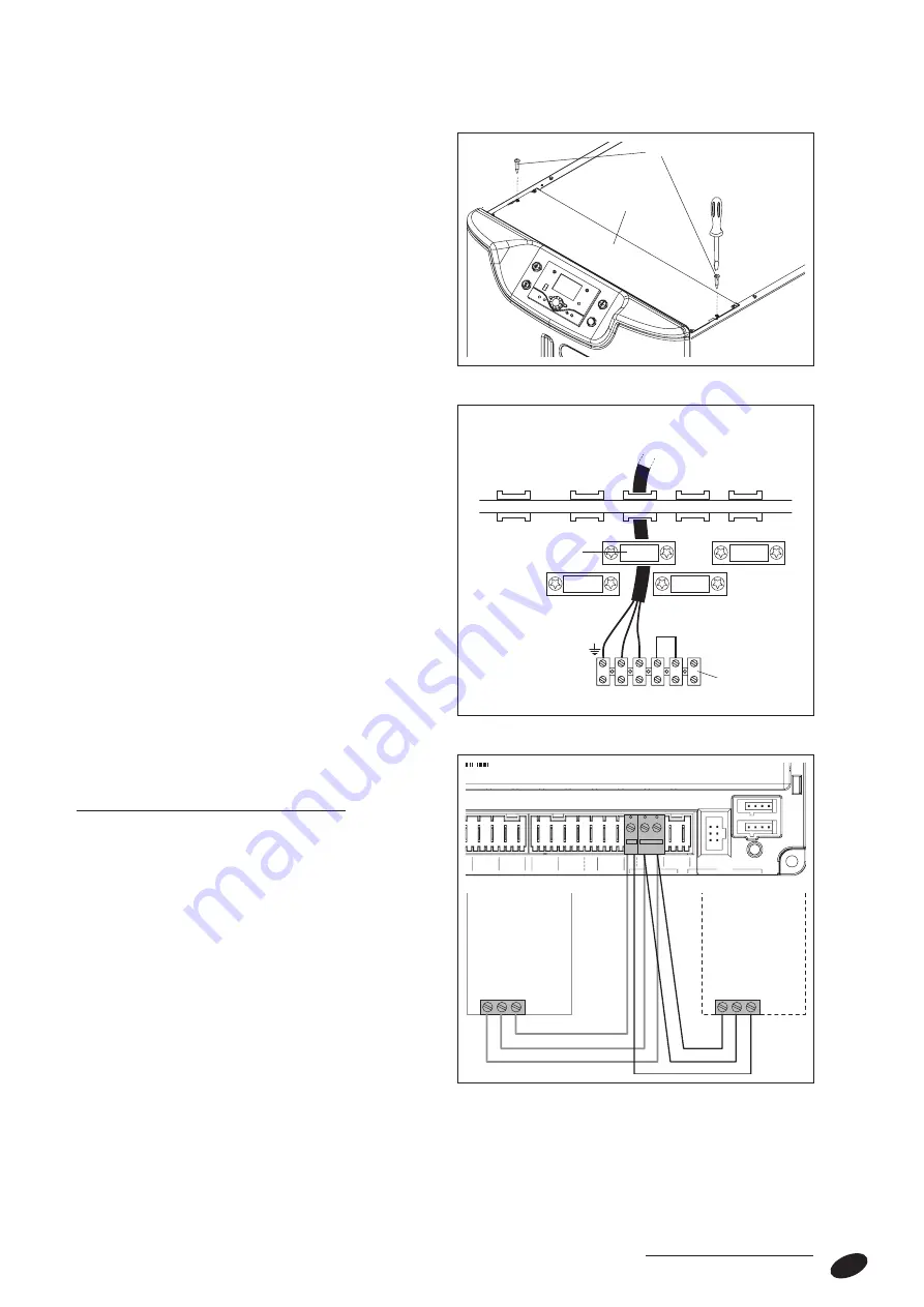
Proceed as follows to make these connections.
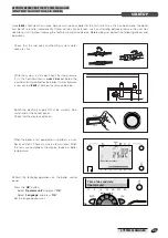
- Pull up and remove the top panel (1) from the boiler
- Unscrew the screws (2) and remove the cover (3) from
over the control panel
- Make the electrical connections to the boiler’s terminal
block (MO1) as shown alongside.
b
Use the cable clamp (P) to hold the mains cable in
place.
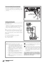
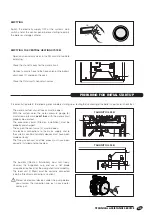
Terminals (2-3) provide a multi-functional input that can
be used to control boiler ignition from a room thermostat
for a direct heating zone.
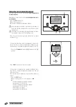
- Connect up the outside sensor (see relevant section).
- Connecting up the room unit (not supplied)
Use a two core cable to connect the room unit to termi-
nals CL+ and CL- on the main board, taking care not to
invert polarity.
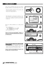
Set the relevant parameters to assign the room unit to
the corresponding circuit (see “Preparing for initial start-
up”).
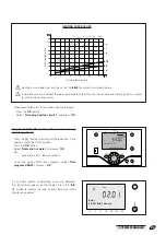
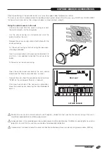
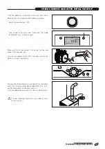
- Once you have made all the necessary connections,
close the control panel, reversing the steps followed to
open it.
L1
N
6 5 4 3 2 1
230 V~50 Hz
MO1
Power supply
P
CL-CL+
G+
1 -
G+
+
2 3
1 -
G+
+
2 3
L1
S3
EX1 S3 T2 T1 N
L1
QX3
N
SK2 SK1
N
N
Y2
QX2
Y1
QX4
Q2
QX5
FX1
QX1
QX1
N
L
P
Q
R
S
T
B
M
M
H1
B9
B3
M
M
M
M BX2
BX1
B1
BX3
M
M
B2
BX5
H3 GX1 M
MB DB
X60
P1
n
n
p
n
k
h
f
n
n
b
a
X30
X50
LPB
BSB
Room
unit
1
Room
unit
2
2
3

