GENERAL
14
TS
TF
H2
L1
N
AP
PE
S3
T1
T2
RS
RS
H1
IMF
L
N
PE
230 V~50 Hz
Y1/QX4
Y2/QX2
BSB
-4p
BSB
NA/0
-10
V
H1
Q2/QX5
QX1
QX1
FX1
QX3
L1
PE
PE
T1
T1
N
N
T2
T2
X30
-10
p
X30
L1
L1
S3
S3
N
N
B1/BX3
BX
1
BX
1
M
B2
B3
B9
M
BX
2
BX
2
LPB
-4p
LPB
M
X50
-5p
X50
X60
-6p
X60
LPB
DB
MB
L
L
PE
PE
S3
S3
4
4
SK
2
SK
2
SK
1
SK
1
N
N
N
N
N
N
PE
PE
FX1
PE
PE
PE
PE
M
TA-M
M
M
M
M
M
M
CL+
CL+
CL+
CL+
CL-
CL-
CL-
CL-
G+
G+
GX1
GX1
H3
H3
M
M
SCH1
M
O
1
FU
6.3
A-T
SC
SE
SMix1
1
N
2
VM
ix1
N
L1
PE
PI
Mix1
N
L1
PE
PB
TA
TA
0
1
IP
TA TA
X
30
T1
T2
T3
T4
T5
T6
T7
T8
SCH2
SB
TSMix1
QX1
QX1
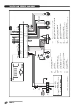
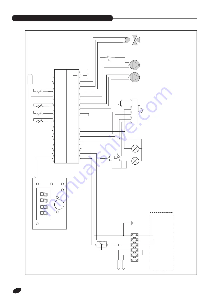
Electrical connections to be made
by the heating engineer
Power supply
open
close
CH 1 phase
Storage
cylinder phase
1st stage
CH 1 snsr
ground
Boiler snsr
DHW 1 snsr
Out. temp. snsr
ground
ground
ground
QX1
IMF
Multifunctional input (*)
FU
Fuse (6.3 A-T)
IP
Main switch
SCH1
Main boar
d
SCH2
Display and contr
ol car
d
TF
Flue gas ther
mostat (90°C)
TS
Safety ther
mostat (110°C +0/-6)
H1
Safety ther
mostat or
flue gas ther
mostat trip indicator
H2
Bur
ner lockout indicator
AP
Bur
ner contr
oller
RS
Remote bur
ner r
eset
QX1
Pr
ogrammable output, parameter 5890
See the water connections section for fur
ther
infor
mation.
PIMix1
Mixed cir
cuit pump (optional)
VMix1
Mixer valve (optional)
PB
Storage cylinder pump (optional)
SC
Boiler sensor
SE
Outside sensor (supplied)
SMix1
Mixed cir
cuit flow sensor (optional)
SB
Storage cylinder sensor (optional)
TSMix1
Mixed cir
cuit safety ther
mostat (not supplied)
(*) See parameters 5950-5951.
Functional wiring diagrams
FUNCTIONAL WIRING DIAGRAMS


