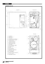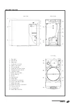
GENERAL
15
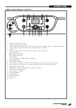
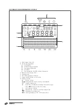
PRIMARY USER INTERFACE / CONTROLS
1
8-9
10
17
11
7
3
2
5 6
4
12
13
15
16
14
8
9
18
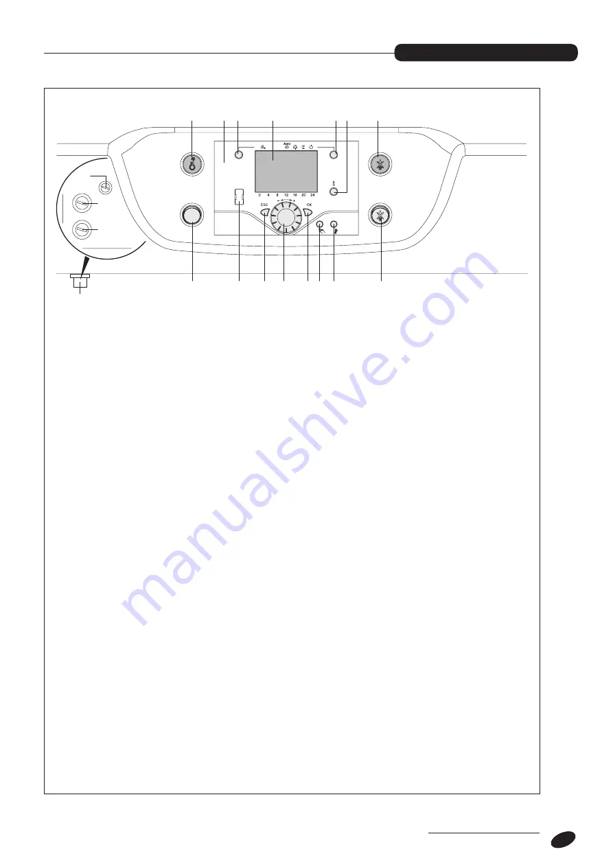
1 - Safety thermostat trip indicator.
2 - Electronic operator unit (controller).
3 - DHW production on/off button (only present if the optional remote storage cylinder is installed). A line appears
under the "
v
" symbol on the display when DHW production is enabled.
4 - Display.
5 - Central heating mode selection button. A line appears under the symbols:
s
AUTOMATIC
o
Continuous COMFORT
l
Continuous REDUCED
F
COOLING
b
Frost protection. The "
t
" symbol is displayed.
6 - Information button "
i
".
7 - Burner lockout indicator.
8 - Manual reset for flue gas thermostat. Unscrew the protective cover to access the reset button.
9 - Manual reset for safety thermostat. Unscrew the protective cover to access the reset button.
10 - Remote burner reset button.
11 - "
p
" button for chimney sweep/safety thermostat test functions.
12 - "
R
" button for manual mode
13 - Value confirm (OK) button.
14 - Value change knob.
15 - ESCape button.
16 - PC BUS connector.
17 - Main switch.
18 - Fuse.
bottom view
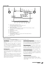
Control panel
CONTROL PANEL


