INSTALLER
39
L1
S3
EX1 S3 T2 T1 N
L1
QX3
N
SK2 SK1
N
N
Y2
QX2
Y1
QX4
Q2
QX5
FX1
QX1
QX1
N
L
P
Q
R
S
T
B
M
M
H1
B9
B3
M
M
M
M BX2
BX1
B1
BX3
M
M
B2
BX5
H3 GX1 M
G+ CL- CL+ MB DB
X60
P1
n
n
p
n
k
h
f
n
n
b
a
X30
X50
LPB
BSB
Main board
OUTSIDE SENSOR
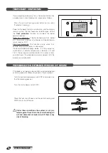
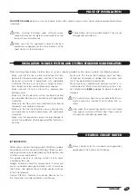
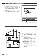
Correct positioning of the outside sensor is essential to proper indoor temperature control.
The sensor must be installed outside the building to be heated, about 2/3 of the way up a NORTH or NORTH-WEST
facing wall, well clear of any flues, doors, windows and out of direct sunlight.
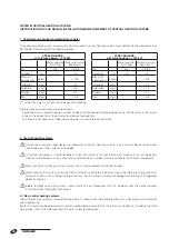
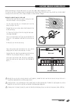
Fixing the outside sensor to the wall
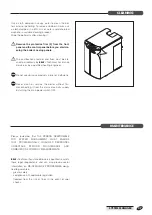
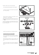
- Unscrew the cover from the sensor casing to access
the terminal block and the fixing holes.
- Use the sensor casing as a template and mark the
points to drill on the wall.
- Remove the sensor casing and drill 5x25 holes for the
expansion plugs.
- Fix the sensor casing to the wall using the two expan-
sion plugs provided.
- Insert a two core cable (with cross section between 0.5
and 1mm
2
, not supplied) to connect the sensor to the
boiler.
- Fit the cover on the sensor casing.
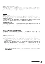
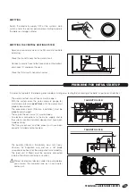
- Open the control panel and identify the main control
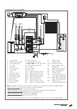
board (see the “Electrical connections” section).
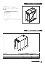
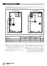
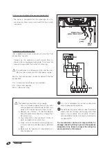
- Connect the wires from the outside sensor to terminals
"M-B9" on the main board. Polarity is irrelevant.
- Once you have made all the necessary connections,
close the control panel, reversing the steps followed to
open it.
b
Position the sensor on a smooth area of wall. Prepare a smooth contact area for the sensor casing if the wall is
made from exposed brick or other rough material.
b
Avoid junctions in the cable between the outside sensor and the control panel. If different cable lengths have to be
joined, make sure that the junctions are sealed and adequately protected.
b
If cable ducts are used to route the sensor connection cable, keep these well clear of any power cables (230Vac).
Outside sensor connections
OUTSIDE SENSOR CONNECTIONS

