background image

10


1.9 

Hydraulic system

Limescale and other chemical substances in the water can so-

lidify producing incrustations. To prevent this happening, equip 

the system with a closed expansion tank. The water that en-

ters the closed expansion tank does not evaporate and is not 

dispersed. In this way the level of water in the system is kept 

constant and it will not be necessary to add fresh water. In ad-

dition, limescale and dust do not form and the system will have 

a longer life.


− The water circulating in the system is not to be used for 

washing or drinking.


− Do not take water from the system. If the water level is 

low, top it up.


− To prevent damage due to limescale or chemical residues, 

put water in the system with the following recommended 

values: pH > 7.2 TH <25 °Fr. Check the water quality, and 

if the quality of the water used does not meet the re-

quired requisites subject the water to suitable corrective 

processes to obtain the required quality.


− To prevent the formation of limescale or sediments inside 

the boiler or their passage from the boiler to the hydraulic 

system, equip the system with suitable protections both 

inside and on the outside.


− Connect the circulation pump to the boiler water outlet. 

The power of the pump should be suitable for the boiler.


− Provide a 4-way mixing valve or a pump on the by-pass 

section activated by a thermostatic control to raise the 

temperature of the water in the return line.


− Provide a 3-way motorised valve connecting the supply 

line and the return line of the heating system, to adjust 

the flow rate of the water in the system according to the 

desired performances.


− The amount of water in the system should be such that 

there is always water in the boiler. Otherwise the boiler 

could be subject to corrosion. If the boiler is not used in 

winter, in order to prevent damage from freezing, use an 

anti-freeze product, periodically measure the amount of 

water in the boiler with a pressure gauge if it has a closed 

expansion tank or with a water gauge if it has an open 

expansion tank.

REFERENCE VALUES

pH

less than 7.2

Electrical conductivity

less than 200 μs/cm (25°C)

Chloride ions

less than 50 ppm

Sulphuric acid ions

less than 50 ppm

Total iron

less than 0.3 ppm

M alkalinity

less than 50 ppm

Total hardness

less than 25° F

Sulphur ions

none

Ammonia ions

none

Silicon ions

less than 30 ppm

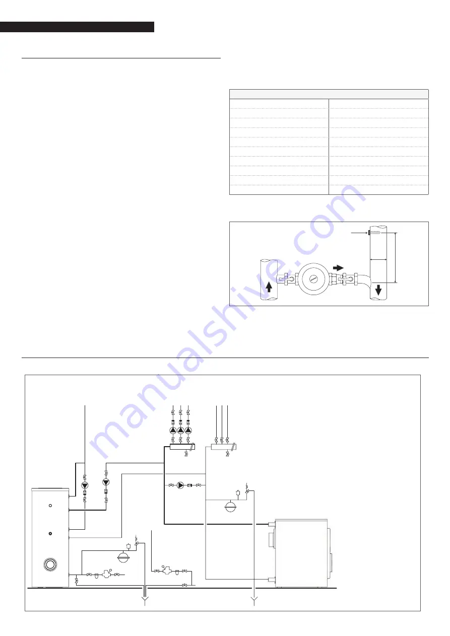
The Thermostat (1) should be installed at a distance of 3-5 diam-

eters from the connection point to the return line.

D

1

3÷5 

D

3

2

2

3

3

3

4

5

3

8

10 15

10

13

14

12

1

EAF

EAF

15

6

3

3

3

3

11

6 7

17 5

3

3

3

5

3

4

3

5

3

4

SYSTEM 

OUTLET

SYSTEM 

RETURN 

LINE

DOMESTIC 

WATER 

UTILITIES

DISCHARGES

DISCHARGES

Boiler 

2  System manifolds

3  Shut-off valves

4  System pumps

5  Non-return valves

6  Automatic vent valve

7  Boiler safety valve

8  Boiler discharge tap

9  Storage heater safety valve

10   Charging the system

11  System expansion tank

12  Storage heater

13  Storage heater discharge tap

14  Domestic hot water expansion 

tank

15  Softener filter

16   Pressure  reducer

17  Condensation pump

1.10 

Schematic diagram - system for heating and domestic hot water production

Summary of Contents for 20091179

Page 1: ...cod Doc 0079319 rev 0 03 2016 RTT 76 145 EN INSTRUCTIONS FOR THE INSTALLER AND FOR THE TECHNICAL ASSISTANCE CENTRE ...

Page 2: ...hnical Assistance Centre which is specifically capable of carrying out routine maintenance keep it running at maximum efficiency with low running costs and which has original spare parts if required This instruction booklet contains important information and suggestions that should be observed for easy installation and better use of the RTT 76 145 boiler Thank you once again Riello S p A CONFORMIT...

Page 3: ...n of the boiler room 12 1 16 Gas side resistor and output temperature of combustion gases 13 1 17 Instructions for use 13 1 18 Conveyance and discharge of the boiler water 13 1 19 Instructions for disposing of the product 13 1 20 Fire prevention regulations for the boiler room 14 1 21 Controls and starting the boiler 14 1 22 Maintenance instructions 15 1 23 Cleaning the boiler 15 1 24 Burner door ...

Page 4: ...the master switch 9 9Especially in summer when the boiler is off for a long pe riod to avoid problems of incrustation in the circulation pumps the boiler must be switched on 1 2 times a month and the circulation pumps operated for at least 5 minutes Limescale in the water can cause problems if the pump is unused for a long period 9 9Choose a boiler with the right dimensions for the project in full...

Page 5: ...iler increases The RTT boilers are made of EN GJL 200 a special alloy that resists expansion and temperature variations which ensures a long working life Thanks to the vertical structures that have been specially de signed with three flue passes the exhaust gases pass three times inside the boiler obtaining a high level of transmission of the heat produced by the combustion to the water present in...

Page 6: ...ater input output coupling G 2 DN Boiler gas volume 64 1 78 36 92 62 106 88 121 14 dm3 lt 0 064 0 078 0 093 0 107 0 121 m2 Combustion chamber gas volume 45 94 56 16 66 38 76 6 86 82 dm3 lt 0 046 0 056 0 066 0 077 0 087 m2 Safety limit thermostat 110 C Type of fuel I2H gas Extra light Fuel Oil comb liquid Flue gases output temperature full load 184 187 179 185 175 182 170 177 169 174 C partial load...

Page 7: ...dimensions 280 550 820 L RTT 76 RTT 93 RTT 110 RTT 128 RTT 145 L mm 800 922 1 044 1 166 1 288 690 544 65 1 6 Delivery The RTT 76 145 boilers are mounted on a wood pallet wrapped with Pluriball and inside a wood box 9 9Comply with the meaning of the symbols on the packaging for reasons of safety ...

Page 8: ... 1 370 L L 200mm 200mm 800mm A Characteristics of the base it should be made of BS 25 fibre concrete it should respect the indicated dimensions it should not be covered with a slippery material like ce ramic etc any acoustic insulation should be made before the base In the RTT 76 145 boilers the door of the burner can open on both sides For this reason equal free distances are specified on both si...

Page 9: ...ntilation 9 9Arrange for the creation of a diversion of the water supply line near the boiler and a drainage system for draining the boiler water 9 9It is strongly recommended not to install extraction systems air conditioning system or other devices that in the boil er room as a secondary effect could cause the so called vacuum effect and reduce the draught force of the boiler with main consequen...

Page 10: ...valve connecting the supply line and the return line of the heating system to adjust the flow rate of the water in the system according to the desired performances The amount of water in the system should be such that there is always water in the boiler Otherwise the boiler could be subject to corrosion If the boiler is not used in winter in order to prevent damage from freezing use an anti freeze...

Page 11: ...th a differ ence of level H between the output of the fuel tank 9 and the burner input 10 greater than 4 m When the boiler is not being used empty the fuel tank to prevent corrosion Low flue edge Bad surface dust etc Blocking gas flow Dust obstacling cleaning Flue which is not available for cleaning Weakly closed door Too long pipe Cleaning door leaking air Objects blocking gas flow Connection bet...

Page 12: ...0 49 29 41 13 94 20 07 18 69 26 91 24 13 34 75 If the fuel is methane gas Type of boiler Cross section of the opening for natural ven tilation cm Volume of air required for forced ventilation Lower part Upper part Lower part Upper part RTT 76 610 163 245 163 RTT 93 689 344 301 201 RTT 110 767 384 358 239 RTT 128 846 423 414 276 RTT 145 924 462 471 314 If natural ventilation is used If forced venti...

Page 13: ...supplied by the manufacturer or distributors Do not switch on the burner un til the circulation has started inside the boiler If the circulation pump or the protection pump are faulty switch off the burner The system should work in a coordinated manner The circulation pump should always be operating when the burner is running Choose a protection pump that is adequate for the boiler output Connect ...

Page 14: ...eaks or faults restore the connec tion before starting the boiler Clean the filters if the boiler runs on gas make sure that the tank is charged and check that the gas valves are open If the boiler runs on liquid fuel check the level in the fuel tank and make sure the fuel valve is open Check the pumps are running and check their rotation direction Check the control panel s electrical system All t...

Page 15: ...ess the following Conditions and sealing of the elements and the insulat ing cords Operating pressure for adjusting the combustion with the combustion gas measurement system if necessary Sensors and connection of the sensors Boiler combustion chamber and any formations of soot in the passages cleaning after checking Fastening and seal of the boiler door Seals of the boiler fittings Correct opening...

Page 16: ...ion 1 is composed of a special thermal ceramic that can withstand up to 1250 ºC and is safe for people to use Be very careful when transporting the insulating plate A ceramic fibre insulating cord is inserted in the door groove The cord has the function of preventing leaks between the door and the front element of the boiler After cleaning or repair work put back the door fixing it solidly to the ...

Page 17: ... 3739700 RTT 145 RG 5D 3739800 DOUBLE FUEL BURNER BOILER BURNER MODEL CODE RTT 76 R40 D17 3482601 RTT 93 R40 D17 3482601 RTT 110 R40 D17 3482601 GAS BURNER BOILER BURNER MODEL CODE RTT 76 BS 3 3761316 RTT 93 BS 3 3761316 RTT 110 BS 3D 3761716 RTT 128 BS 3D 3761716 RTT 145 BS 3D 3761716 1 25 Table of burner combinations ...

Page 18: ...sported ensure at least the normal storage conditions non aggressive environment air humidity less than 75 temperature between 5 and 55 c low dust levels and the prevention of damage due to biological factors Do not force the cover elements and the boiler panels in the storage phase or when being transported 9 9For the transportation of the boiler always use lift trucks transpallets or other means...

Page 19: ...ormation Retailer Mr Address Tel Technical Assistance Centre Mr Address Tel Installer Mr Address Tel Date Intervention Fuel supplier Mr Address Tel Date Qty supplied Date Qty supplied Date Qty supplied Date Qty supplied ...

Page 20: ...ago VR Tel 0442630111 Fax 044222378 www riello it As part of the company s ongoing commitment to perfecting its range of products the appearance dimensions technical data equipment and accessories may be subject to variation ...

Reviews: