background image


2044


3


GB


WORKING RANGE


TEST BOILER


The working field has been defined according to DIN 4788 and EN 676 standards.


COMMERCIAL BOILERS


The burner-boiler matching is assured if the boiler is according to EN 303 and the combustion
chamber dimensions are similar to those shown in the diagram EN 676.

For applications where the boiler is not according to EN 303, or where the combustion chamber
dimensions differ from those shown in EN 676, please consult the manufacturers.


CORRELATION BETWEEN GAS PRESSURE AND BURNER OUTPUT


To obtain the maximum output, a gas head pressure of 4.6 mbar is measured with the combustion
chamber at 0 mbar using gas G20 with a net heat value of  10 kWh/m


3


 (8,570 kcal/m


3


).

0.8

0

0.2

0.4

0.6

Pressure in the comb

ustion

c

hamber – mbar

20,000

30,000

40,000

50,000

kcal/h

20

40

30

50

60

kW

Burner output

D5135

1.0

16

15,000

Gas pressure

mbar

4

1

2

3

5

6

D5136

20,000

30,000

40,000

50,000

kcal/h

20

40

30

50

60

kW

Burner output

16

15,000

0

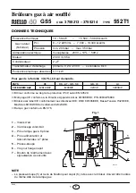
Summary of Contents for 3755213

Page 1: ...tenance instructions Montage und Bedienungs Anleitung Gas Gebl sebrenner Br leurs gaz air souffl Forced draught gas burners CODE MODELL MODELE MODEL TYP TYPE 3755213 GS5 552T1 3755214 GS5 552T1 D F GB...

Page 2: ......

Page 3: ...Befestigung der Haube werden auf der gleichen Seite der Gasstrecke installiert Nennw rmebelastungsbereich 18 58 kW 15 500 50 000 kcal h Gas 2 Gasfamilie Unterer Heizwert 8 12 kWh m3 7 000 10 340 kcal...

Page 4: ...1 2 180 138 A1 D5065 Menge Beschreibung 1 4 1 1 1 1 7 poliger Stecker Schrauben mit Mutter Flanschdichtung Schraube f r Befestigung der Haube Kabeldurchf hrung Schwenkgelenk Den Brennkopf durch L sen...

Page 5: ...303 und der EN 676 entspricht m ssen die technischen Daten aufeinander abgestimmt werden Die Kesselda ten beim Hersteller abfragen VOM GASDRUCK ABH NGIGE BRENNERLEISTUNG Bei einem an dem Verbindungsro...

Page 6: ...RONORM EN 676 MULTIBLOC DUNGS ANSCHL SSE GEBRAUCH RIELLO GASSTRECKE alternativ GASSTRECKE BRENNER MBDLE 403 B01 Rp 1 2 Rp 1 2 Erdgas 40 45 kW Fl ssiggas Filter DUNGS GF 505 1 Gasdruckregler DUNGS FRS...

Page 7: ...Erdung Flammenf hler Z ndelektrode 1 2 3 N Ph B4 S3 T2 T1 N 3 6 5 8 12 4 7 2 9 1 STEUERGER T 525SE 5 1 2 3 4 N L P M 1 2 P D5125 Schwarz Braun Blau Luftklappenstellmotor M Luftdruckw chter Schwarz Ko...

Page 8: ...gef hrten elektrischen Verbindungen m ssen den Landesbestimmungen entsprechen PROGRAMMABLAUF DES BRENNERSTARTS Sollte die Flamme w hrend des Betriebes erl schen schlie t das Ventil innerhalb 1 Sekunde...

Page 9: ...en da die r ckw rtige Fl che C des Verbin dungsrohres mit der gew nschten Skala Einstellzahl bereinstimmt Die Schraube A wieder festziehen Beispiel Der Brenner ist auf einem Kessel von 40 kW installie...

Page 10: ...rend der Einregulierung des Gasbrenners wird der Luftdruck w chter auf 0 gestellt Ist die Einregulierung abgeschlossen wird der Luftdruck einregu liert Die Regulierskala langsam im Uhrzeigersinn drehe...

Page 11: ...rabschaltung er folgt w hrend der Vor sp lphase Der Luftdruckw chter schaltet nicht um er ist defekt oder der Luftdruck ist zu gering Brennerkopf ist schlecht eingestellt Die Flamme wird simuliert ode...

Page 12: ......

Page 13: ...le br leur doivent tre mont s du m me c t de la rampe gaz Puissance thermique 18 58 kW 15 500 50 000 kcal h Gaz naturel Famille 2 Pci 8 12 kWh m3 7 000 10 340 kcal m3 Pression min 20 mbar max 35 mbar...

Page 14: ...70 91 233 10 140 Rp 1 2 180 138 A1 D5065 Quantit D nomination 1 4 1 1 1 1 Fiche 7 p les Vis avec crous Joint isolant Vis pour fixation capot Presse toupe Charni re Enlever ensuite la t te de combustio...

Page 15: ...i n est pas conforme la norme EN 303 ou dont les dimensions de la chambre de combustion sont plus petites que celles indiqu es dans la norme EN 676 consulter le fabriquant CORRELATION ENTRE PRESSION D...

Page 16: ...4 5 6 7 8 1 Conduit arriv e du gaz 2 Robinet de barrage charge de l installateur 3 Manom tre pression du gaz charge de l installateur 4 Filtre 5 Pressostat gaz 6 Vanne de s curit 7 R gulateur de press...

Page 17: ...r Terre br leur Connecteur Antiparasite Sonde Electrode d allumage 1 2 3 N Ph B4 S3 T2 T1 N 3 6 5 8 12 4 7 2 9 1 BOITE DE CONTROLE 525SE 5 1 2 3 4 N L P M 1 2 P D5125 Noir Marron Bleu M Noir Condensat...

Page 18: ...rieur la bo te de contr le Les branchements lectriques ex cut s par l installateur doivent respecter le r glement en vigueur dans le Pays CYCLE DE DEMARRAGE Si la flamme s teint durant le fonctionnem...

Page 19: ...r le coude B de fa on ce que la surface post rieure du manchon C cor responde avec l encoche d sir e Serrer la vis A Exemple Le br leur est mont sur une chaudi re de 40 kW Supposant un rendement de 90...

Page 20: ...le pressostat air r gl en d but d chelle Avec le br leur fonctionnant au minimum de puissance augmen ter la pression du r glage en tournant lentement le bouton gradu dans le sens horaire jusqu l arr...

Page 21: ...rmateur d allumage L air n a pas t vacu de la conduite Le br leur se met en s curit pendant la phase de pr venti lation Le pressostat air n etablit pas le contact il est d fectueux ou bien la pression...

Page 22: ......

Page 23: ...h the burner must be fitted to the same side of the gas train Thermal output 18 58 kW 15 500 50 000 kcal h Gas Family 2 Net heat value 8 12 kWh m3 7 000 10 340 kcal m3 Pressure min 20 mbar max 35 mbar...

Page 24: ...91 233 10 140 Rp 1 2 180 138 A1 D5065 Quantity Description 1 4 1 1 1 1 7 pin plug Screws with nuts Insulating gasket Screw for fixing the cover Cable gland Hinge Separate the combustion head assembly...

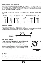
Page 25: ...tion chamber dimensions differ from those shown in EN 676 please consult the manufacturers CORRELATION BETWEEN GAS PRESSURE AND BURNER OUTPUT To obtain the maximum output a gas head pressure of 4 6 mb...

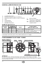
Page 26: ...5 B01 Rp 1 2 Rp 1 2 Natural gas and LPG 1 D5050 M2 2 3 M1 4 5 6 7 8 1 Gas supply pipe 2 Manual cock charged to the installer 3 Gas pressure gauge charged to the installer 4 Filter 5 Gas pressure switc...

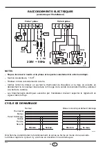
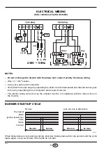
Page 27: ...lue Motor Burner earth Connector Suppressor Ionization probe Ignition electrode 1 2 3 N Ph B4 S3 T2 T1 N 3 6 5 8 12 4 7 2 9 1 CONTROL BOX 525SE 5 1 2 3 4 N L P M 1 2 P D5125 Black Brown Blue Damper ac...

Page 28: ...d connector The electric wiring carried out by the installer must be in compliance with the rules in force in the Country BURNER START UP CYCLE When flame failure occurs during working shut down takes...

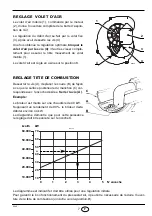
Page 29: ...screw A move the elbow B so that the rear plan of the coupling C coincides with the set point Tight the screw A Example The burner is installed on a 40 kW boiler with an effi ciency of 90 the burner i...

Page 30: ...her adjustments have been made Begin with the switch at the lowest setting With the burner working at the minimum output adjust the dial clockwise increasing its value until the burner shuts down Now...

Page 31: ...air The burner does not pass through the pre purge peri od and the control box goes to lock out The air pressure switch does not change over it has failed or the air pressure is too low combustion hea...

Page 32: ......

Reviews: