2044
6
GB
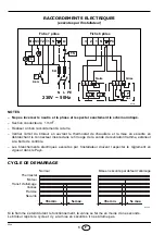
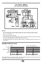
ELECTRICAL WIRING
(to be carried-out by the installer)
NOTES
– Do not exchange the neutral with the phase and connect exactly the above wiring.
– Wire of 1 mm
2
section.
– Carry out a safe earth connection.
– Verify that the burner stops by operating the boiler control thermostats and that the burner goes
lock out by separating the red ionisation probe lead connector.
– The electric wiring carried out by the installer must be in compliance with the rules in force in
the Country.
BURNER START-UP CYCLE
When flame-failure occurs during working, shut down takes place within one second; and the cycle
starts again; a lock-out follows if the flame do not start.
B4 S3 T2 T1
L1
N
Black
N L PE
h
TS
P
VS
V1
1 2 3
1 2 3
GAS
230V
~
50Hz
D5127
3
2
1 N
Ph
T
Grey
6A
ADJUST.
7 pin plug
6 pin plug
Normal
Lock-out, due to light-failure
Thermostat
Motor
Ignition transformer
Valve
Flame
Lock-out
35s min.
5s max.
35s min.
5s max.
D5048


