9
20146122
GB
Technical description of the burner
4.6
Firing rate
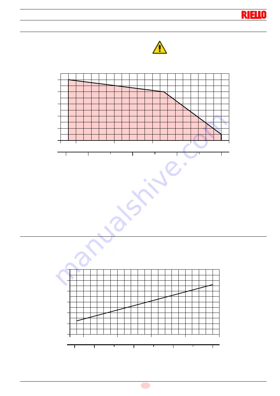
The burner output is chosen from within the diagram area (Fig. 2).
4.6.1
Test boiler
The firing rate has been defined according to EN 676 standard.
4.6.2
Commercial boilers
The burner-boiler matching is assured if the boiler conforms to
EN 303 and the combustion chamber dimensions are similar to
those shown in the diagram EN 676.
For applications where the boiler does not conform to EN 303, or
where the combustion chamber is much smaller than the dimen-
sions given in EN 676, please consult the manufacturers.
4.7
Correlation between gas pressure and burner output
To obtain the maximum output (Fig. 3), it is necessary to have 4.6
mbar measured on the pipe coupling, with the combustion cham-
ber at 0 mbar and gas G20 - NCV = 10 kWh/Nm
3
(8,570 kcal/
Nm
3
).
ATTENTION
The firing rate value (Fig. 2) has been obtained
considering an ambient temperature of 20°C, an
atmospheric pressure of 1013 mbar (approx. 0m
above sea level), and with the combustion head
adjusted as shown on page 16.
Combu
stio
n chambe
r
pressure -
mbar
Fig. 2
Thermal power
0.8
0
0.2
0.4
0.6
15,000
20,000
30,000
50,000
kcal/h
16
20
30
60 kW
D5135
1.0
40
50
40,000
16
20
30
40
50
60 kW
15,000
20,000
30,000
40,000
50,000
kcal/h
6
5
4
0
1
2
3
Thermal power
D5136
Fig. 3
Gas pressure to t
he
combustio
n h
ead
-
mba
r


