11
20146103
GB
Technical description of the burner
4.10
Electrical control box
The control box is a control and supervision system for forced
draught burners, for intermittent operation (at least one controlled
shutdown every 24 hours).
Important notes
All interventions (assembly and installation operations,
assistance, etc.) must be carried out by qualified personnel.
Before modifying the wiring in the control box connection
area, fully disconnect the system from the power supply
(omnipolar separation).
Protection against electrocution from the control box and all
connected electric components is obtained with the correct
assembly.
Before any intervention (assembly and installation opera-
tions, assistance, etc.), ensure the wiring is in order and that
the parameters are correctly set, then make the safety
checks.
Falls and collisions can negatively affect the safety func-
tions.
In this case, the control box must not be operated, even if it
displays no evident damage.
For safety and reliability, comply with the following instruc-
tions:
-
Avoid conditions that can favour the development of conden-
sate and humidity. Otherwise, before switching on again,
make sure the control box is perfectly dry.
-
Static charges must be avoided since they can damage the
control box’s electronic components when touched.
Installation notes
•
Check the electrical wiring inside the boiler complies with the
national and local safety regulations.
•
Install switches, fuses, earth connection etc. in compliance
with local regulations.
•
Do not confuse the powered conductors with the neutral
ones.
•
Ensure that spliced wires cannot get into contact with neigh-
bouring terminals. Use adequate ferrules.
•
Arrange the H.V. ignition cables separately, as far as possi-
ble from the control box and the other cables.
•
When wiring the unit, make sure the 230V AC mains voltage
cables are run strictly separate from extra low-voltage cables,
to avoid the risk of electrocution.
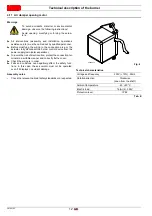
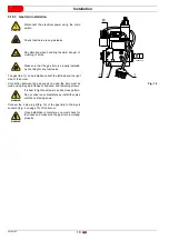
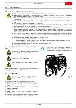
To remove the control box from the burner it is necessary to (Fig.
5):
disconnect all the connectors connected to it, all the plugs,
the high voltage cables and the earth wire (
TB
);
unscrew the screw (
A
) and pull the control box in the direc-
tion of the arrow.
To install the control box it is necessary to:
tighten the screw (
A
) with a tightening torque of 1 - 1.2 Nm;
reconnect all previously disconnected connectors, making
sure to connect the 7 pin power plug as the final step.
NOTE:
The burners have been approved for intermittent operation.
This means that they must stop once every twenty four
hours to permit the electrical control box to check its effi-
ciency at start up. The boiler limit thermostat (TL) normally
ensures the stopping of the burner. If this is not the case, it
is necessary to apply a timer switch in series to the limit
thermostat (TL) that turns off the burner at least once every
24 hours.
Electrical wiring of ionisation probe
It is important for signal transmission to be almost totally free
of any disturbances or loss:
•
Always separate the probe cables from the other cables:
- the line capacity reduces the magnitude of the flame sig-
nal;
- use a separate cable.
•
The cable length must not exceed 1 m.
•
Respect the polarity
•
Insulation resistance
- must be at least 50 M
between the ionisation probe and
the earth;
- a dirty detector reduces the insulation resistance, fostering
leakage currents.
•
The ionisation probe is not protected against the risk of elec-
trocution. When connected to the electricity supply, the ioni-
sation probe must be protected against any accidental
contact.
•
Position the ionisation probe so that the ignition spark cannot
form an arc on the probe (risk of electric overcharge).
Technical data
Tab. D
WARNING
To avoid accidents, material or environmental
damage, observe the following instructions!
The control box is a safety device! Avoid opening
or modifying it, or forcing its operation. The Man-
ufacturer cannot assume any responsibility for
damage resulting from unauthorised work!
Mains voltage
AC 210...230 V -15 % / +10 %
Mains frequency
50/60 Hz ±6 %
Built-in fuse
T5A 250V
Energy consumption
40 VA
Protection level
IP00
Fig. 5
E9324
Summary of Contents for 40 FS5D
Page 2: ...Translation of the original instructions...
Page 41: ......
Page 42: ......
Page 43: ......


