20146103
16
GB
Installation
5.8
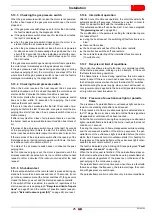
Combustion head adjustment
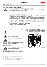
To adjust, proceed as follows:
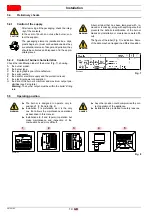
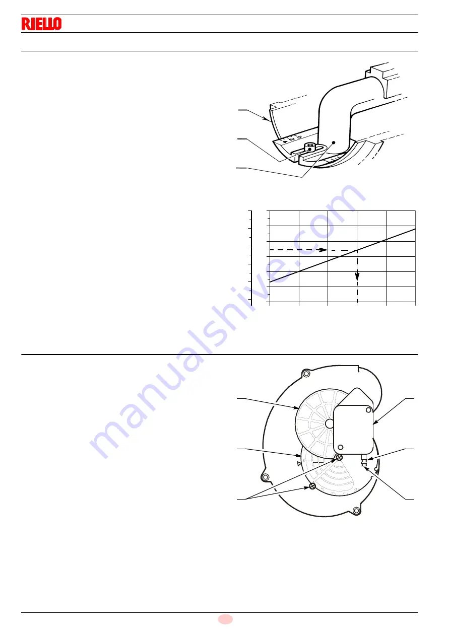
loosen the screw A)(Fig. 12), move the elbow B) so that the
rear plate of the coupling (C) coincides with the set point;
tighten the screw A).
Example:
The burner is installed in a 40 kW boiler.
Considering efficiency of 90% the burner must supply around 44
kW.
The diagram (Fig. 13) shows that for this output the adjustment
must be made on notch 3.
The diagram is to be used only for initial settings,. To ensure
good air pressure switch operation it may be necessary to reduce
this combustion head opening (notch toward pos. 0).
5.9
Air dampers adjustment
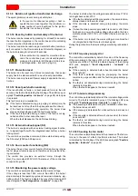
To adjust, proceed as follows:
Take the burner to the 2nd stage.
The mobile air damper 1)(Fig. 14), activated by the motor 2),
ensures the suction inlet opens completely.
Adjust 2nd stage air delivery using the fixed damper 3) after
loosening the screws 4).
Once optimal adjustment has been attained, fully screw in
the screws 4).
The damper leaves the factory set at pos.6, as shown in Fig. 14.
Take the burner to the 1st stage.
The mobile air damper (1) returns to the standby position.
Adjust 1st stage air delivery by turning the screw (6) after
loosening the nut (5) by turning it in a clockwise direction.
Once the ideal setting has been reached, block the nut (5)
by turning it in an anticlockwise direction.
C
A
B
S7015
Fig. 12
Fig. 13
kcal/h
kW
D5137
Notch No.
70
50
40
30
20
10
60
40,000
50,000
30,000
20,000
10,000
60,000
0
2
1
3
4
5
44
Fig. 14
D5074
1
3
2
6
5
4
Summary of Contents for 40 FS5D
Page 2: ...Translation of the original instructions...
Page 41: ......
Page 42: ......
Page 43: ......

