31
ENDKONTROLLEN
• Den Foto-Widerstand verdunkeln und die Fern-
steuerungen schließen: der Brenner muß ein-
schalten und ca. 5 s nach Ventilöffnung der 1.
Stufe in Störabschaltung fahren.
• Den Foto-Widerstand beleuchten und die Fern-
steuerungen schließen: der Brenner muß ein-
schalten und ca. 10 s danach in
Störabschaltung fahren.
• Den Foto-Widerstand mit Brennerbetrieb auf 2.
Stufe verdunkeln, es muß folgender Ablauf
stattfinden: Erlöschen der Flamme in 1 s, ca.
20s Belüftung, ca. 5 s Zündfunken, Störab-
schaltung des Brenners.
• Die Fernsteuerung TL und anschließen auch
TS bei funktionierendem Brenner öffnen: der
Brenner mu anhalten.
WARTUNG
Verbrennung
Die Abgase der Verbrennung analysieren.
Bemerkenswerte Abweichungen im Vergleich
zur vorherigen Überprüfung zeigen die Stelle
an, wo die Wartung aufmerksamer ausgeführt
werden soll.
Pumpe
Der Druck im Auslass muß stabil auf 12 bar blei-
ben.
Der Unterdruck muß unter 0,45 bar liegen.
Das Geräusch der Pumpe darf nicht wahrnehm-
bar sein.
Im Fall von Druckschwankungen oder geräus-
chvoll arbeitender Pumpe den Schlauch vom
Linienfilter abhängen und den Brennstoff aus ei-
nem Tank in der Nähe des Brenners ansaugen.
Mit diesem Trick kann festgestellt werden, ob die
Ansaugleitung oder die Pumpe für das Geräusch
verantwortlich ist.
Ist es die Pumpe, kontrollieren Sie, ob ihr Filter
verschmutzt ist. Da der Vakuummeter oberhalb
des Filters angebracht ist, kann er nämlich nicht
feststellen, ob dieser verschmutzt ist.
Liegt die Ursache der Störung indessen an der
Ansaugleitung, kontrollieren Sie, ob der Linienfil-
ter verschmutzt ist oder Luft in die Leitung ein-
tritt.
Filter
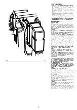
Die Filtersiebe kontrollieren, Abb.A S.22:
• der Linie 3) • in der Pumpe 2) • an der Düse ,
reinigen oder auswechseln.
Falls im Innern der Pumpe Rost oder andere
Verunreinigungen bemerkt werden, mit einer
separaten Pumpe Wasser und andere, eventuell
abgelagterte Verschmutzungen vom Tankboden
absaugen.
Gebläse
Prüfen Sie, ob im Innern des Gebläses und auf
seinen Schaufeln Staubablagerungen vorhan-
den sind: diese vermindern den Luftdurchfluß
und verursachen folglich eine umweltbelastende
Verbrennung.
Flammkopf
Kontrollieren Sie, ob alle Teile des Flammkopfs
ganz, nicht von der hohen Temperatur verformt,
frei von Verunreinigungen aus der Umwelt und
korrekt ausgerichtet sind.
Düsen
Eine Reinigung der Düsenbohrung ist zu
vermeiden. Es wird empfohlen, die Düsen
einmal pro Jahr im Zuge der periodischen
Wartung zu tauschen. Das Auswechseln der
Düsen erfordert eine Kontrolle der Verbrennung.
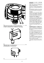
Foto- Widerstände
Das Glas von eventuellem Staub befreien. Den
lichtelektrischen Widerstand 1) kräftig nach
außen ziehen; um ihn auszurasten.
Schläuche
Kontrollieren Sie, ob der Zustand der Schläuche
gut ist und sie nicht etwa verformt sind.
Tank
Ungefähr alle 5 Jahre muß das eventuell auf
dem Tankboden angesammelte Wasser mit
einer separaten Pumpe abgesaugt werden.
Kessel
Reinigen Sie den Kessel laut den mitgelieferten
Anleitungen, so daß die ursprünglichen Verbren-
nungsdaten erneut erhalten werden, und zwar
im besonderen Druck in der Brennkammer und
Abgastemperaturen.
FINAL CHECKS
• Obscure the photocell and switch on the con-
trol devices: the burner should start and then
lock-out about 5 s after opening of the 1st stage
operation valve.
• Illuminate the photocell and switch on the con-
trol devices: the burner should start and then
go into lock-out after about 10 s.
• Obscure the photocell while the burner is in
2nd stage operation, the following must occur
in sequence: flame extinguished within 1 s,
purging for about 20 s, sparking for about 5 s,
burner goes into lock out.
• Switch off control device TL followed by control
device TS while the burner is operating: the
burner should stop.
MAINTENANCE
Combustion
The optimum calibration of the burner requires
an analysis of the flue gases. Significant differ-
ences with respect to the previous measure-
ments indicate the points where more care
should be exercised during maintenance.
Pump
The delivery pressure must be stable at 12 bar.
The depression must be less than 0.45 bar.
Unusual noise must not be evident during pump
operation.
If the pressure is found to be unstable or if the
pump runs noisily, the flexible hose must be de-
tached from the line filter and the fuel must be
sucked from a tank located near the burner. This
measure permits the cause of the anomaly to be
traced to either the suction piping or the pump.
If the pump is found to be responsible, check to
make sure that the filter is not dirty. The vacuum
meter is installed upstream from the filter and
consequently will not indicate whether the filter is
clogged or not.
Contrarily, if the problem lies in the suction line,
check to make sure that the filter is clean and
that air is not entering the piping.
Filters
Check the following filter boxes, fig. A page 22:
• on line 3) • in the pump 2) • at the nozzle , and
clean or replace as required.
If rust or other impurities are observed inside the
pump, use a separate pump to lift any water and
other impurities that may have deposited on the
bottom of the tank.
Fan
Check to make sure that no dust has accumulat-
ed inside the fan or on its blades, as this condi-
tion will cause a reduction in the air flow rate and
provoke polluting combustion.
Combustion
H
ead
Check to make sure that all the parts of the com-
bustion head are in good condition, positioned
correctly, free of all impurities, and that no defor-
mation has been caused by operation at high
temperatures.
Nozzles
Do not clean the nozzle openings.
It is advisable to replace nozzles every year dur-
ing regular maintenance operations.
The change of nozzle requires the combustion to
be controlled.
Photocell
Clean the glass cover from any dust that may
have accumulated. Photocell 1) is held in posi-
tion by a pressure fit and can therefore be re-
moved by pulling it outward forcefully.
Flexible hoses
Check to make sure that the flexible hoses are
still in good condition and that they are not
crushed or otherwise deformed.
Fuel tank
Approximately every 5 years, or whenever nec-
essary, suck any water or other impurities pres-
ent on the bottom of the tank using a separate
pump.
Boiler
Clean the boiler as indicated in its accompanying
instructions in order to maintain all the original
combustion characteristics intact, especially the
flue gas temperature and combustion chamber
pressure.
CONTROLES FINAUX
• Obscurcir la photorésistance et fermer les
télécommandes: le brûleur doit démarrer et se
bloquer 5 secondes environ après l’ouverture
de la vanne de 1ère allure.
• Eclairer la photorésistance et fermer les
télécommandes: le brûleur doit démarrer et,
après environ 10 secondes, se bloquer.
• Obscurcir la photorésistance brûleur fonction-
nant en 2° allure, on doit avoir en séquence:
extinction de flamme dans la seconde qui suit,
ventilation pendant 20 secondes environ, énti-
celle pendant 5 secondes environ et blocage
du brûleur.
• Ouvrir d’abord la télécommande TL et ensuite
TS, brûleur en marche: le brûleur doit s’arrêter.
ENTRETIEN
Combustion
Pour obtenir un réglage optimal du brûleur, il
faut effectuer l'analyse des gaz d'échappement
de la combustion à la sortie de la chaudière. Les
différences significatives par rapport au contrôle
précédent indiqueront les points où l'opération
d'entretien devra être plus approfondie.
Pompe
La pression en refoulement doit être stable à 12
bar.
La dépression doit être inférieure à 0,45 bar.
Le bruit de la pompe ne peut pas être gênant.
En cas de pression instable ou de pompe bruy-
ante, retirer le tuyau flexible du filtre de ligne et
aspirer le combustible d'un réservoir situé à
proximité du brûleur. Cette opération permet de
repérer si c'est le tuyau d'aspiration qui est re-
sponsable de l'anomalie ou bien la pompe.
Si c'est la pompe, contrôler que son filtre ne soit
pas sale. En effet, le vacuomètre étant monté en
amont du filtre ne détecte pas l'état d'encrasse-
ment.
Si au contraire, la cause des anomalies est liée
au tuyau d'aspiration, contrôler qu'il n'y ait pas de
filtre de ligne encrassé ou de pénétration d'air
dans le tuyau.
Filtres
Contrôler les éléments filtrants, Fig. A page 22:
• de ligne 3) • sur la pompe 2) • au gicleur ,
les nettoyer ou les remplacer.
Si on remarque à l'intérieur du brûleur de la
rouille ou d'autres impuretés, aspirer du fond de
la cuve avec une pompe séparée, l'eau et les im-
puretés qui s'y sont éventuellement déposées.
Ventilateur
Vérifier qu'il n'y ait pas de poussière accumulée
à l'intérieur du ventilateur et sur les palettes de la
turbine: cette poussière réduit le débit d'air et
produit par conséquent une combustion pollu-
ante.
Tete de combustion
Vérifier que toutes les parties de la tête de com-
bustion soient intactes, non déformées par la
haute température, privées d'impuretés prove-
nant du milieu environnant et positionnées cor-
rectement.
Gicleurs
Eviter de nettoyer le trou des gicleurs.
Il est conseillé de remplacer les gicleurs toutes
les années lors de l'entretien périodique.
Le changement des gicleurs implique un
contrôle de la combustion.
Photoresistance
Eliminer éventuellement la poussière sur la vitre.
Pour extraire la photorésistance 1) tirer celle-ci
de façon énergique vers l'extérieur; elle est in-
sérée uniquement sous pression.
Tuyaux flexibles
Contrôler qu'ils soient en bon état et qu'ils n'aient
pas été écrasés ou déformés.
Cuve
Tous les 5 ans environ, selon les besoins, aspir-
er l'eau ou les impuretés qui ont pu se déposer
dans le fond de la cuve, en utilisant une pompe
séparée.
Chaudiere
Nettoyer la chaudière selon les instructions
fournies, de manière à pouvoir retrouver les don-
nées de combustion originales, en particulier:
pression dans la chambre de combustion et
température fumées.
Summary of Contents for 966 T
Page 45: ...45 RL 300 B MZ...
Page 46: ...46 RL 400 B MZ...
Page 47: ...47...
Page 48: ...48 RL 300 B MZ...
Page 49: ...49 0 1 1 1 2 3 2 RL 400 B MZ...
Page 50: ...50 01123 0 3 112 01453 6 7 0 3 8 9 0 3 112 01453 6 7 8 9 8 8 9 8 9 76 76 A...
Page 53: ......
Page 54: ......
Page 55: ......

