20094575
30
GB
Start-up, calibration and operation of the burner
5.4
Combustion air adjustment
Fuel/combustion air must be synchronized with the relevant servo-
motors (air and gas) by storing a setting curve by means of the
electronic cam.
To reduce pressure loss and to have a wider adjustment range, it
is best to set the servomotor to the maximum output used, as near
to maximum opening (90°) as possible.
On the gas butterfly valve, the fuel’s partial setting adjustment
based on required output, with the servomotor fully open, is made
by using the pressure stabilizer on the gas train.
With O
2
control via the relative kit, follow the instructions about
commissioning in the specific handbook for the LMV52.... instru-
ment provided at the Technical Service Training.
5.4.1
Adjusting gas/air delivery
Move slowly towards the maximum output (butterfly gas valve
completely open);
adjust the required maximum output with the gas pressure sta-
bilizer;
adjust the combustion parameters with the air servomotor and
store the maximum combustion point;
complete the procedure slowly, synchronizing the combustion
with the two servomotors and storing the different setting
points.
5.4.2
Air/fuel control and power modulation system
The air/fuel and power modulation system installed on
RS
burner
series provides, a set of integrated functions ensuring top level en-
ergy and operational performance from the burner, both for single
and grouped burners (e.g. boiler with a double combustion cham-
ber or several generators in parallel).
The system includes the following basic functions:
air and fuels are supplied in correct quantities by positioning
the valves by direct servo-control, thus avoiding the possibility
of play typical of systems used for traditional modulating burn-
ers, in which settings are obtained by levers and a mechanical
cam;
burner power is modulated according to the load required by
the system, while boiler pressure or temperature is maintained
at set operating values;
fine, continuous correction of the airflow according to the anal-
ysis of the flue gases at the stack (O
2
); this function is associ-
ated with the O
2
kit containing the PLL module and the QGO2
sensor;
measurement of the combustion efficiency; this function is
associated with the O
2
kit;
a sequence (cascade control) of several boilers by suitably
connecting different units.
Further interfaces and computer communication functions for re-
mote control or integration in centrally supervised systems are
available according to the system’s configuration.
NOTE
The first start-up and all further operations concerning internal set-
tings of the control system or expansion of basic functions, are ac-
cessed with a password and are reserved for technical service
personnel specifically trained for internal programming of the in-
strument and for the specific application obtained with this burner.
The first start-up and curve synchronization manual is supplied with
the burner.
The complete manual for checking and setting all parameters will
be provided on application.
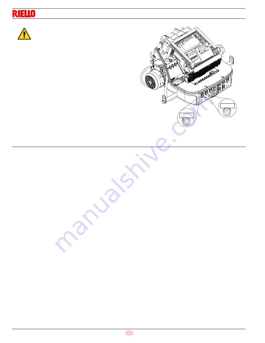
WARNING
For the start-up procedure and the parameters
calibration, refer to the specific instruction man-
ual of the LMV37... electronic cam supplied with
the burner.
REMOTE
LOCAL
ON OFF
Fig. 35
20097538
Summary of Contents for C9327710
Page 2: ...Original instructions ...
Page 43: ......


