20102152
34
GB
Maintenance
6.4
Opening the burner
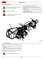
In order to open the burner, proceed as follows:
loosen the 4 screws 1)(Fig. 42) and remove the cover 2);
install the 2 extensions 9) on the sliding bars 4) and re-screw
the screws 8);
remove the screws 3) and pull back the burner on the sliding
bars 4) of about 4”;
disconnect the electrode lead, then unthread the burner com-
pletely from the sliding bars;
remove the screw 6) and extract the inner part 5) of the head.
6.5
Closing the burner
In order to close the burner, re-install all components with reverse
procedure:
remove the 2 extensions 9) and re-screw the screws 8) on the
sliding bars 4) ;
push the burner up to approximately 4” from the pipe coupling;
reinsert the electrode lead and slide the burner as far as the
stop.
fix the screws 3) to secure the burner to the combustion head;
fix the 4 screws 1) to install the cover 2).
DANGER
Disconnect the electrical supply from the burner by
means of the main system switch.
DANGER
Close the fuel interception tap.
Wait for the components in contact with heat sourc-
es to cool down completely.
4
5
6
1
3
7
1
2
9
8
4"
Fig. 42
20097483
WARNING
Connect the electrical supply from the burner.


