Installation
21
20102152
GB
4.11
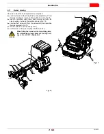
Burner closing
Once the combustion head adjustment is completed:
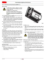
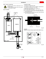
push the burner on the sliding bars 3) at approximately 4” from
the pipe coupling 4) - burner in the position shown in Fig. 18;
insert the electrode cable, then slide the burner as far as the
pipe coupling - burner in the position shown in Fig. 19;
unscrew the 2 screws 2) from the extension 5) and reposition
them as previously Fig. 19.
refit the screws 2) on the sliding bars 3);
fix the burner to the pipe coupling with the screws 1).
WARNING
When fitting the burner on the two sliding bars,
it is advisable to gently draw out the high volt-
age cable until it is slightly taut.
4"
2
5
3
4
1
Fig. 18
D10593
6
6
6
5
5
Fig. 19
20097397


