background image

20102152

GB

Technical description of the burner

3.1

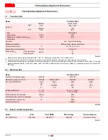
Technical data

Tab. A

(1)

Reference conditions: Ambient temperature 68 °F (20 °C) - Barometric pressure 394” WC - Altitude 329 ft.

(2)

Pressure at test point 21)(Fig. 5), with zero pressure in the combustion chamber, with open gas ring at maximum burner output

(3)

Sound pressure measured in manufacturer's combustion laboratory, with burner operating on test boiler and at maximum rated output. The sound
power is measured with the “Free Field” method, as per EN 15036, and according to an “Accuracy: Category 3” measuring accuracy, as set out in EN
ISO 3746.

3.2

Electrical data

Tab. B

3.3

Burner models designation

Tab. C

3

Technical description of the burner

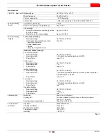
Model

RS 120/EV BLU

Output 

(1)

High

MBtu/hr

kW

2282 - 4924

666 - 1443

Low

MBtu/hr

kW

1136

333

• Fuel

Natural gas

• Max delivery
• Pressure at maximum delivery 

(2) 

natural gas

SCFH

“WC

4924

8.85

Operation

Low - high or modulating

Standard application

Boilers: water, steam, thermal oil

Ambient temperature

°F

32 - 104 (0 - 40 °C)

Combustion air temperature

°F max

140 (60 °C)

Noise levels 

(3)

Sound pressure
Sound power

dB(A)

77
89

Model

RS 120/EV BLU

Control circuit power supply

V/Ph/Hz

120/1/60

Main power supply (+/-10%)

V/Ph/Hz

208-230/3/60

460/3/60

575/3/60

Fan motor IE2/EPACT

tr/min

HP

V
A

3500

3

208-230

7.8

3500

3

460

3.9

3500

3

575

3.1

Ignition transformer

V1 - V2

I1 - I2

120 V - 1 x 8 kV

1.6 A - 20 mA

Electrical power consumption

W max

2600

Electrical control circuit consumption

W

750

Total electrical consumption

W

3350

Electrical protection

NEMA 1

Model

Code

Code RBNA

Main Voltage

Flame safeguard

RS 120/EV BLU

20101539

C9343710

460/3/60

Burner mounted

Summary of Contents for C9343710

Page 1: ...20102152 3 09 2017 Installation use and maintenance instructions Forced draught gas burner Progressive two stage or modulating operation CODE MODEL C9343710 RS 120 EV BLU GB...

Page 2: ...Original instructions...

Page 3: ...Actuators SQM33 5 15 4 Installation 16 4 1 Notes on safety for the installation 16 4 2 Handling 16 4 3 Preliminary checks 16 4 4 Operating position 17 4 5 Preparing the boiler 17 4 5 1 Introduction 1...

Page 4: ...5 2 Maximum gas pressure switch 31 5 5 3 Minimum gas pressure switch 31 5 6 Final checks with the burner working 31 6 Maintenance 32 6 1 Notes on safety for the maintenance 32 6 2 Maintenance program...

Page 5: ...car ried out correctly may cause damage to the ma chine and or injury to people DANGER DANGER LIVE COMPONENTS This symbol indicates operations which if not car ried out correctly lead to electric shoc...

Page 6: ...of damage to things or injury to peo ple if such damage injury was due to any of the following causes incorrect installation start up use and maintenance of the burner improper incorrect or unreasona...

Page 7: ...nce Only those parts envisaged by the manufacturer can be replaced 2 2 Personnel training The user is the person body or company that has acquired the ma chine and intends to use it for the specific p...

Page 8: ...Output 1 High MBtu hr kW 2282 4924 666 1443 Low MBtu hr kW 1136 333 Fuel Natural gas Max delivery Pressure at maximum delivery 2 natural gas SCFH WC 4924 8 85 Operation Low high or modulating Standard...

Page 9: ...on of the combustion head requires the burner to be opened and the rear part drawn back on the sliding bars The dimensions of the open burner are indicated by position I Tab E 3 6 Burner equipment The...

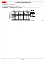
Page 10: ...le 100 ft 0 36 F Example Rated Capacity 2517 MBtu hr Rated Air Pressure 1 39 WC Reference Altitude 328 ft Reference Temperature 20 C 68 F Real Altitude 3000 ft Real Temperature 17 C 62 6 F Temperature...

Page 11: ...3 Average barometric pressure 68 F WC 399 394 385 371 358 345 332 320 307 294 1 CORRECTED BURNER AIR PRESSURE ACCORDING TO ALTITUDE Altitude Rated Pressure WC m a s l 0 100 305 610 915 1220 1525 1830...

Page 12: ...mum furnace dimensions The firing rate was set in relation to certified test boilers Fig 4 indicates the diameter and length of the test combustion chamber Example output 2579 Mbtu hr diameter 24 inch...

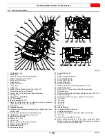
Page 13: ...an to pipe coupling 27 Switch LOCAL REMOTE 28 Gas butterfly valve 29 Boiler fixing flange 30 Flame stability disc 31 Horn 32 Button ALARM SILENCE 33 Signal POWER ON 34 Signal IGNITION ON 35 Signal FUE...

Page 14: ...cuits via which it is possible to easily identify any causes of malfunctioning Mechanical design The following system components are integrated in the LMV37 4 basic unit Burner control with gas valve...

Page 15: ...nal voltage Nominal current Power factor AC 120 V 50 60 Hz 1 6 A pilot duty load declaration to UL372 cos 0 4 Alarm output Nominal voltage Nominal current Power factor AC 120 V 50 60 Hz 1 A cos 0 4 Ig...

Page 16: ...T P 10 Shutdown Operation Startup Valve proving OUTPUTS INPUTS Phase number Fuel Actuator 2 Air Actuator 1 Actuators Safety limit thermostat STB Control thermostat or pressurestat R Flame signal FS Ai...

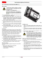
Page 17: ...can be seen on the dis play of the Operator Panel Index 0 for fuel actuator index 1 for air actuator Installation notes Always run the high voltage ignition cables separate from the unit and other ca...

Page 18: ...ated in this manual and in compliance with the standards and regulations of the laws in force WARNING The handling operations for the burner can be high ly dangerous if not carried out with the greate...

Page 19: ...nt direction compared with the oth ers With the kit this second group of tubes is substituted so that all the tubes are the same After assembling the kit check its efficiency by measuring the flue gas...

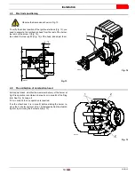
Page 20: ...refractory lining is not necessary 11 12 Fig 12 unless expressly requested by the boiler manufacturer 4 7 Securing the burner to the boiler Detach the combustion head from the burner Fig 12 loosen th...

Page 21: ...tion head At this point check whether the maximum delivery of the burner at high fire operation is contained in area A or in area B of the firing rate See Fig 3 at page 8 If it is in area A then no op...

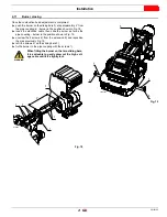
Page 22: ...ex 6 Tighten the 3 screws 1 fully down Example burner output 3750 MBtu hr If we consult diagram Fig 16 we find that for this output the ad justments are air R1 notch 2 gas R2 notch 5 Note Diagram Fig...

Page 23: ...de the burner as far as the pipe coupling burner in the position shown in Fig 19 unscrew the 2 screws 2 from the extension 5 and reposition them as previously Fig 19 refit the screws 2 on the sliding...

Page 24: ...bustion head within the safety time of 3s Ensure that the maximum pressure necessary for the burner is in cluded in the calibration field of the pressure regulator colour of the spring The pilot gas t...

Page 25: ...C 5 11 1 18 3 93 WC A maximum output of 3030 MBtu hr shown diagrams corresponds to 3 93 WC pressure This value serves as a rough guide the effective delivery must be measured at the gas meter NOTE To...

Page 26: ...ectrical supply of the burner corresponds to that shown on the identification label and in this manual Do not invert the neutral with the phase in the electrical supply line Any inversion would cause...

Page 27: ...shown in Fig 25 Key Fig 25 1 Motor supply cable 2 Single phase supply cable 3 Connecting cable between the inverter and the electronic cam WARNING It is very important to shield the motor cable 1 as...

Page 28: ...the case of clamp type B pull the indicated tabs upwards and lift until locked in the open position B1 Fig 26 insert the shielded cable with the shielding inside the clamp B2 put pressure on the indic...

Page 29: ...lamping the cable to the earth plate The screen must be earthed on both side of the cable take care for good earthing system Examples Number 1 2 3 show not proper ways to earth a cable screen WARNING...

Page 30: ...ors manufactured for 208 230 460 IE3 NEMA Premium Efficiency voltage have the same connection than IE2 Epact motors but differ ent connection than IE1 motors no more star delta but star double star D3...

Page 31: ...ssure switches set the parameters on the RWF55 regulator Please refer to the specific manual for this operation Turn the switch of Fig 35 to position ON and turn the switch of Fig 35 to position LOCAL...

Page 32: ...burner locks out again turn the knob counter clockwise a little bit more DANGER As the burner is not fitted with a device to check the sequence of the phases the motor rotation may be incorrect As so...

Page 33: ...r operating at MAX output increase adjustment pressure by slowly turning the relative dial clockwise until the burn er locks out Then turn the dial anti clockwise by 0 8 WC and repeat burner starting...

Page 34: ...h the UV scanner Fig 40 proceed as follows extract the UV scanner 2 clean the glass cover from any dust that may have accumu lated Fan Check to make sure that no dust has accumulated inside the fan or...

Page 35: ...comply with the regulations in force or at any rate do not produce good combustion Use the appropriate card to record the new combustion values they will be useful for subsequent controls 6 3 Flame si...

Page 36: ...der to close the burner re install all components with reverse procedure remove the 2 extensions 9 and re screw the screws 8 on the sliding bars 4 push the burner up to approximately 4 from the pipe c...

Page 37: ...ndix Spare parts 31 34 10 1 2 3 4 6 21 27 26 52 50 28 52 52 54 60 35 46 30 37 33 39 38 36 53 69 55 58 56 70 62 50 32 32 5 23 13 23 25 12 51 40 14 19 47 48 16 59 8 7 17 44 48 22 18 20 49 9 47 48 57 43...

Page 38: ...BLY C 21 20030200 MOTOR 2 2 KW C 22 3014106 FUSE 6 3A A 23 20036017 GREEN SIGNAL LIGHT C 24 20042704 SPEED SENSOR 25 20027014 WHITE SIGNAL LIGHT C 26 3013681 SCREW C 27 3003891 CONNECTOR C 28 3014079...

Page 39: ...extended safety fittings 52 3013937 HUB 53 301249 SCREW 54 3012639 CONTROL DEVICE 55 20030203 SHUTTER C 55 20030202 SHUTTER C 56 20030204 BRACKET 57 20086579 UV PHOTOCELL A 58 20030206 END CONE 59 302...

Page 40: ...Tubes kit Gas train according to UL Standards B Appendix Accessories Burner Code RS 120 EV BLU 3010248 WARNING The installer is responsible for the supply and instal lation of any required safety dev...

Page 41: ...2 Low Fire High Fire Main Power Supply O2 Low Fire High Fire Control Power Supply CO Low Fire High Fire Burner Firing Rate NOX Low Fire High Fire Manifold Pressure Net Stack Temp Low Fire High Fire Pi...

Page 42: ......

Page 43: ......

Page 44: ...URNERS NORTH AMERICA 35 Pond Park Road http www riello ca 2165 Meadowpine Blvd Hingham Massachusetts Mississauga Ontario U S A 02043 1 800 4 RIELLO Canada L5N 6H6 RIELLO S p A I 37045 Legnago VR Tel 3...

Reviews: