2916050
10
GB
Technical description of the burner
3.8
Firing rates
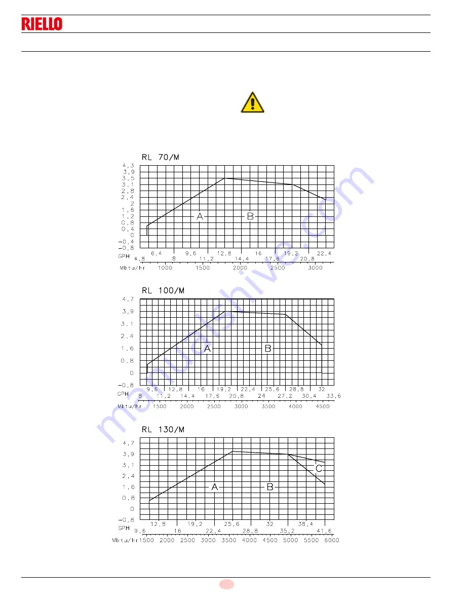
During operation, burner output varies between:
–
minimum output
: area A;
–
maximum output
: area B (and C for model RL 130/M).
The firing rate may be found by plotting a vertical line from the de-
sired delivery and a horizontal line from the pressure in the com-
bustion chamber. The intersection of these two lines is the firing
rate which must lie within area A, for MIN output, and within area
B, for MAX output.
In order to utilize also area C (RL 130/M) it is necessary to perform
the calibration of the combustion head as explained on page 18.
NOTE:
The firing rate areas given in Fig. 4 have been reduced by 10%
with respect to the maximum range that can be reached.
Consult the Procedure below to refer burner operating condition in
high altitude plants.
WARNING
The firing rate area values have been obtained con-
sidering an ambient temperature of 68 °F (20°C),
and an atmospheric pressure of 394” WC and with
the combustion head adjusted as shown on page 7.
D2350
Fig. 4
C
ombustion
cha
m
ber
pres
sure -
“WC
Combu
stio
n ch
amber
pressure -
“WC
Combustio
n ch
amber
pr
essure -
“WC


