Installation
19
2916050
GB
4.11 Hydraulic system
4.11.1 Fuel supply
Double-pipe circuit
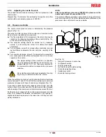
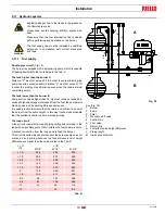
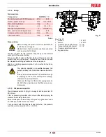
The burner is equipped with a self-priming pump which is capable
of feeding itself within the limits listed in the Tab. K.
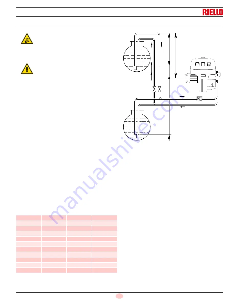
The tank higher than the burner A
Distance "P" must not exceed 33 ft in order to avoid subjecting the
pump's seal to excessive strain; distance “V” must not exceed 13 ft
in order to permit pump self-priming even when the tank is almost
completely empty.
The tank lower than the burner B
Pump suction values higher than 13” Hg must not be exceeded be-
cause at higher levels gas is released from the fuel, the pump starts
making noise and its working life-span decreases.
It is good practice to ensure that the return and suction lines enter
the burner from the same height; in this way it will be less probable
that the suction line fails to prime or stops priming.
The loop circuit
A loop circuit consists of a loop of piping exiting and returning to the
tank with an auxiliary pump that circulates the fuel under pressure.
A branch connection from the loop goes to feed the burner.
This circuit is extremely useful whenever the burner pump does not
succeed in self-priming because the tank distance and/or height
difference are higher than the values listed in the Tab. K.
Tab. K
Burner
2
Pump
3
Filter
4
Manual on/off valve
5
Suction line
6
Foot valve
7
Return line
H
Pump/foot valve height difference
L
Piping length
Ø Inside pipe diameter
Explosion danger due to fuel leaks in the presence
of a flammable source.
Precautions: avoid knocking, attrition, sparks and
heat.
Make sure that the fuel interception tap is closed
before performing any operation on the burner.
WARNING
The fuel supply line must be installed by qualified
personnel, in compliance with current standards
and laws.
+/- H
(ft)
L (ft)
Ø 3/8”
Ø 1/2”
Ø 5/8”
+ 13
234
454
493
+ 10
204
401
493
+ 6.6
174
399
493
+ 3.3
145
296
493
+ 1.6
132
270
493
0
118
243
451
- 1.6
105
217
405
- 3.3
92
191
359
- 6.6
63
138
266
- 10
33
86
174
- 13
–
33
82
A
B
1
2
3
7
5
6
6
4
7
5
- H
+ H
V
P
D737
3
15
/ 16
”
Fig. 18


