Installation
23
2916050
GB
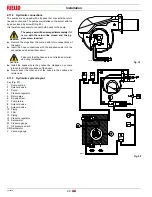
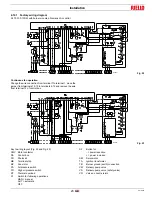
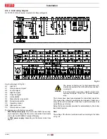
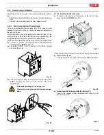
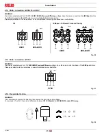
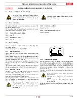
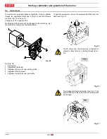
4.12.1 Factory wiring diagram
RL 70-100-130/M with burner mounted Siemens LAL control.
Continuous fan operation
Change the wire connection from terminal 7 to terminal 1, move the
jumper from terminals 12-13 to terminals 4-12 and remove the wire
from terminal 13 of control box.
Key to wiring layout (Fig. 22 and Fig. 23)
CMV Motor contactor
DA
Control box
FR
Photocell
MB
Terminal strip
MV
Fan motor
PA
Air pressure switch
PO
High oil pressure switch
RT
Thermal overload
S1
Switch for following operations:
MAN = manual
AUT = automatic
OFF
S2
Button for:
- = power reduction
+ = power increase
SM
Servomotor
TA
Ignition transformer
TB
Burner ground (earth) connection
VM
Delivery pump valve
VS
Delivery pump valve (safety valve)
VR
Valve on nozzle return
Fig. 22
D2815
Fig. 23
D2873


