2916050
24
GB
Installation
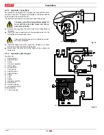
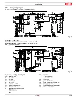
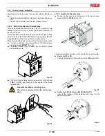
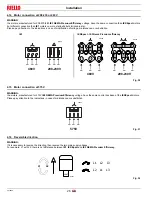
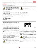
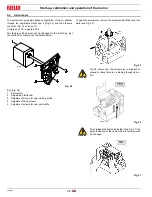
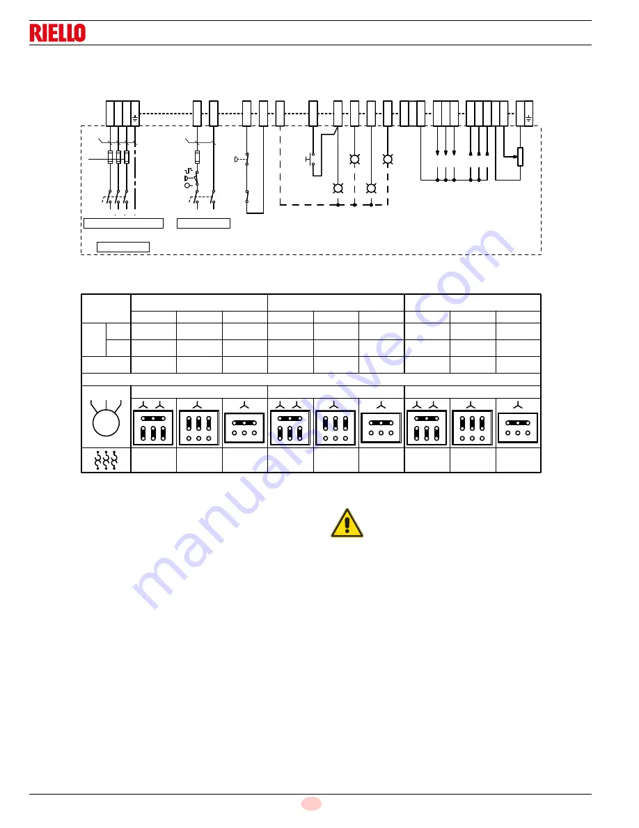
4.12.2 Field wiring diagram
RL 70-100-130/M with burner mounted LAL flame safeguard.
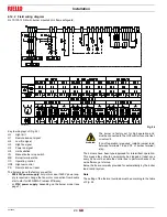
Key to wiring layout (Fig. 24)
HL
High limit
H1
Remote lock-out signal
H2
Low fire signal
H3
High fire signal
H4
Power on signal
H5
Limit satisfied
IN
Manual burner stop switch
MB
Burner terminal strip
OC
Operating control
OC2 High-low control
PS
Remote lock-out reset
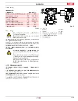
The burners leave the factory pre-set for:
–
208-230V power supply
: only in this case, if 460 V power sup-
ply is required, change the fan motor connection from double
star to star for IE3 NEMA Premium Efficiency;
–
or
575V power supply
: depending on the burner model (see
The burners have been type-approved for intermittent operation.
This means they should compulsorily be stopped at least once
every 24 hours to enable the control box to perform checks of its
own efficiency at start-up.
Burner halts are normally provided for automatically by the boiler
load control system.
Note
The setting of the thermal overload must be according to the table
of Fig. 24.
! "#
$%
"#
$%
!
&
&
'()
" "!
* '+,
! "# $%
"# $%
'()
'()
!"! * &
" "!
* '+,
!
#
'()
" "!
* '+,
"
"
'()
" "!
* '+,
&
!"! $ " %
'()
!"! &
" "!
* '+,
'()
" "!
* '+,
! -
'()
" "!
* '+,
---
!"&"
---'
---'
---
'()
!"! * &
" "!
* '+,
%
# &"
---'
%
---'
%
.
%
---
'()
" "!
* '+,
! -
&
Fig. 24
20120355
WARNING
The burner is factory set for high operation and
must be connected to the OC2 control to control fuel
oil valve V2.
If on-off operation is required, install a jumper lead
between terminals T6 and T8 of burner terminal
strip.


