Faults - Probable causes - Solutions
35
2916050
GB
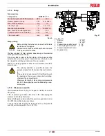
The control box is equipped with a lockout indicator (Fig. 49) that
turns during the start-up programme, and is visible from the small
lockout window.
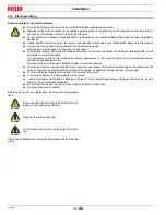
When the burner does not start or stops, due to a failure, the sym-
bol that appears on the indicator indicates the type of interruption.
The positions of the lockout indicator are shown in Fig. 50.
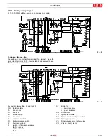
Fuse replacement
The fuse 2)(Fig. 51) is in the rear part of the control box. A spare
fuse 1) is also available: it can be extracted after breaking the panel
tab A) that houses it. In the event that fuse 2) has been tripped, re-
place it as shown in Fig. 51.
Find a list of faults, causes and possible solutions for a set of fail-
ures that may occur and result in irregular burner operation or no
functioning at all.
If a burner malfunction is detected, first of all:
–
check that the electrical wiring is adequately connected;
–
check whether fuel is delivered;
–
check that every adjustment parameter is adequately set.
7
Faults - Probable causes - Solutions
Fig. 49
S8889
Lockout indicator
a-b
Start-up sequence
b-b’
Idle stages (without con-
tact confirmation)
b(b’)-a
Post-purging programme
P
1
2
Fig. 50
S8888
WARNING
In the event of a burner lockout, more than two
consecutive burner reset operations could cause
damage to the installation. On the third lockout,
contact the Aftersales Service.
DANGER
If further lockouts or burner faults occur, interven-
tions must only be made by qualified, authorised
personnel (as indicated in this manual, and in
compliance with the laws and regulations current-
ly in force).
T6,3H
250V
1
2
A
Fig. 51
S8884

