background image

20026767

10 

Technical description of the burner

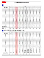
CORRECTED BURNER CAPACITY ACCORDING TO ALTITUDE

Altitude

Rated Capacity 

m a.s.l.

0

100

305

610

915

1220

1525

1830

2135

2440

ft a.s.l

0

328

1000

2000

3000

4000

5000

6000

7000

8000

500

494

500

512

530

551

571

593

616

641

669

1000

987

1000

1023

1061

1101

1142

1186

1232

1282

1337

1500

1481

1500

1535

1591

1652

1713

1778

1848

1924

2006

2000

1974

2000

2046

2121

2202

2284

2371

2464

2565

2675

2500

2468

2500

2558

2652

2753

2855

2964

3079

3206

3343

3000

2962

3000

3069

3182

3303

3425

3557

3695

3847

4012

3500

3455

3500

3581

3712

3854

3996

4149

4311

4488

4680

4000

3949

4000

4092

4243

4404

4567

4742

4927

5130

5349

4500

4442

4500

4604

4773

4955

5138

5335

5543

5771

6018

5000

4936

5000

5116

5303

5505

5709

5928

6159

6412

6686

5500

5429

5500

5627

5834

6056

6280

6520

6775

7053

7355

6000

5923

6000

6139

6364

6606

6851

7113

7391

7694

8024

6500

6417

6500

6650

6894

7157

7422

7706

8006

8335

8692

7000

6910

7000

7162

7425

7708

7993

8299

8622

8977

9361

7500

7404

7500

7673

7955

8258

8564

8892

9238

9618

10029

8000

7897

8000

8185

8485

8809

9135

9484

9854

10259

10698

8500

8391

8500

8697

9016

9359

9705

10077

10470

10900

11367

9000

8885

9000

9208

9546

9910

10276

10670

11086

11541

12035

9500

9378

9500

9720

10076

10460

10847

11263

11702

12183

12704

10000

9872

10000

10231

10607

11011

11418

11855

12318

12824

13373

Average barometric 
pressure (20°C)

mbar

1013

1000

977.4

942.8

908.2

875.8

843.5

811.85

779.8

747.8

Average barometric 
pressure (68°F)

"w.c.

399

394

385

371

358

345

332

320

307

294

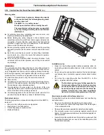
CORRECTED BURNER AIR PRESSURE ACCORDING TO ALTITUDE

Altitude

Rated Pressure

m a.s.l.

0

100

305

610

915

1220

1525

1830

2135

2440

ft a.s.l

0

328

1000

2000

3000

4000

5000

6000

7000

8000

0.50

0.49

0.50

0.51

0.53

0.55

0.57

0.59

0.62

0.64

0.67

1.00

0.99

1.00

1.02

1.06

1.10

1.14

1.19

1.23

1.28

1.34

1.50

1.48

1.50

1.53

1.59

1.65

1.71

1.78

1.85

1.92

2.01

2.00

1.97

2.00

2.05

2.12

2.20

2.28

2.37

2.46

2.56

2.67

2.50

2.47

2.50

2.56

2.65

2.75

2.85

2.96

3.08

3.21

3.34

3.00

2.96

3.00

3.07

3.18

3.30

3.43

3.56

3.70

3.85

4.01

3.50

3.46

3.50

3.58

3.71

3.85

4.00

4.15

4.31

4.49

4.68

4.00

3.95

4.00

4.09

4.24

4.40

4.57

4.74

4.93

5.13

5.35

4.50

4.44

4.50

4.60

4.77

4.95

5.14

5.33

5.54

5.77

6.02

5.00

4.94

5.00

5.12

5.30

5.51

5.71

5.93

6.16

6.41

6.69

5.50

5.43

5.50

5.63

5.83

6.06

6.28

6.52

6.77

7.05

7.35

6.00

5.92

6.00

6.14

6.36

6.61

6.85

7.11

7.39

7.69

8.02

6.50

6.42

6.50

6.65

6.89

7.16

7.42

7.71

8.01

8.34

8.69

7.00

6.91

7.00

7.16

7.42

7.71

7.99

8.30

8.62

8.98

9.36

7.50

7.40

7.50

7.67

7.96

8.26

8.56

8.89

9.24

9.62

10.03

8.00

7.90

8.00

8.18

8.49

8.81

9.13

9.48

9.85

10.26

10.70

8.50

8.39

8.50

8.70

9.02

9.36

9.71

10.08

10.47

10.90

11.37

9.00

8.88

9.00

9.21

9.55

9.91

10.28

10.67

11.09

11.54

12.04

9.50

9.38

9.50

9.72

10.08

10.46

10.85

11.26

11.70

12.18

12.70

10.00

9.87

10.00

10.23

10.61

11.01

11.42

11.86

12.32

12.82

13.37

Average barometric

pressure (20°C)

mbar

1013

1000

977.4

942.8

908.2

875.8

843.5

811.85

779.8

747.8

Average barometric

pressure (68°F)

"w.c.

399

394

385

371

358

345

332

320

307

294

1

2

Summary of Contents for C9541400

Page 1: ...20026767 3 10 2012 Installation use and maintenance instructions Forced draught gas burner Progressive two stage or modulating operation Code Model C9541400 RS 45 E LN GB...

Page 2: ......

Page 3: ...the air fuel ratio LMV37 4 12 3 11 Actuators SQM33 5 15 4 Installation 16 4 1 Notes on safety for the installation 16 4 2 Handling 16 4 3 Preliminary checks 16 4 4 Boiler plate 16 4 5 Blast tube lengt...

Page 4: ...tenance 26 6 1 Notes on safety for the maintenance 26 6 2 Opening the burner 27 6 2 1 To open the burner 27 6 2 2 To close the burner 27 A Appendix Spare parts 28 B Appendix Accessories 31 C Appendix...

Page 5: ...nerator is to be installed The instruction manual shows the serial number of the burner the address and telephone number of the nearest Assis tance Centre The system supplier carefully informs the use...

Page 6: ...manual 1 2 1 Owner s responsibility Please pay attention to the Safety Warnings contained within this instruction manual Keep this manual for your records and provide it to your quali fi ed service a...

Page 7: ...the burner components is not allowed apart from the parts requiring maintenance Only those parts envisaged by the manufacturer can be replaced 2 2 Personnel training The user is the person body or co...

Page 8: ...hr kW 717 2037 1969 210 597 577 Low MBtu hr kW 341 100 Fuel Natural or propane gas Max delivery Pressure at maximum delivery 2 natural gas SCFH WC 2037 5 31 Operation Low high low or modulating Stand...

Page 9: ...e and air fuel ratio 24 Local remote manual selector 25 Fan motor with capacitor 26 Ground terminals 27 Auxiliary fuse 28 Burner ON OFF selector 29 Power ON signal 30 Call for heat lamp 31 Ignition ON...

Page 10: ...the burner to be opened and the rear part withdrawn on the slide bars The maximum dimension of the burner when open without casing is give in measurement H Tab C 1 Blast tube short long obtainable wit...

Page 11: ...ariation reference temper ature 68 F 20 C To get the combined correction in case of different air temper ature a compensation of 1000 ft each 20 F 305 m each 11 C is applicable 100 ft 2 F Example Rate...

Page 12: ...908 2 875 8 843 5 811 85 779 8 747 8 Average barometric pressure 68 F w c 399 394 385 371 358 345 332 320 307 294 CORRECTED BURNER AIR PRESSURE ACCORDING TO ALTITUDE Altitude Rated Pressure m a s l 0...

Page 13: ...he best results are obtained in terms of low NOx emissions The maximum thickness of the boiler s front door must not ex ceed 8 see Fig 5 3 9 Minimum furnace dimensions The firing rates were set in rel...

Page 14: ...s via which it is possible to easily identify any causes of malfunctioning Mechanical design The following system components are integrated in the LMV37 4 basic unit Burner control with gas valve prov...

Page 15: ...oltage Nominal current Power factor AC 120 V 50 60 Hz 1 6 A pilot duty load declaration to UL372 cos 0 4 Alarm output Nominal voltage Nominal current Power factor AC 120 V 50 60 Hz 1 A cos 0 4 Ignitio...

Page 16: ...T P 10 Shutdown Operation Startup Valve proving OUTPUTS INPUTS Phase number Fuel Actuator 2 Air Actuator 1 Actuators Safety limit thermostat STB Control thermostat or pressurestat R Flame signal FS Ai...

Page 17: ...s can be seen on the dis play of the Operator Panel Index 0 for fuel actuator index 1 for air actuator Installation notes Always run the high voltage ignition cables separate from the unit and other c...

Page 18: ...urner must be carried out by qualified personnel as indicated in this manual and in compliance with the standards and regulations of the laws in force WARNING The handling operations for the burner ca...

Page 19: ...must not compromise the extraction of the blast tube For boilers having a water cooled front the insulation 4 5 Fig 11 is not required unless it is required by the boiler man ufacturer 4 6 Securing t...

Page 20: ...he air and the gas and then proceed as follows Outside air adjustment R1 Fig 13 Turn screw 4 until the notch identified is aligned with the front surface 5 of the flange Gas adjustment R3 Fig 13 Loose...

Page 21: ...e extract the inner part of the combustion head 12 4 9 Gas piping The main gas train must be connected to the gas attachment 1 Fig 17 using flange 2 gasket 3 and screws 4 supplied with the burner The...

Page 22: ...proximate maximum output of the burner as fol lows subtract the combustion chamber pressure from the gas pres sure measured at test point 1 Fig 19 find the nearest pressure value to your result in col...

Page 23: ...ts Check that the electrical supply of the burner corresponds to that shown on the identification label and in this manual Do not invert the neutral with the phase in the electrical supply line Any in...

Page 24: ...e motor is 400V To reset in the case of an intervention of the thermal relay press the button RESET Fig 21 The button STOP Fig 21 opens the NC 95 96 contact and stops the motor To test the thermal rel...

Page 25: ...mum safe ty i e with gas delivery at the minimum 5 3 Burner firing Having completed the checks indicated in the previous heading the pilot of the burner should fire If the motor starts but the flame d...

Page 26: ...peration Turn the switch to position ON Fig 29 and the switch of to posi tion LOCAL 5 6 Air pressure switch The air pressure switch is connected in differential Fig 30 and is activated by both the neg...

Page 27: ...tion manual The value during the operation must be higher than 24 If at the burner start up the value is higher or equal of 18 the burner locks out due to the extraneous light The display Fig 32 shows...

Page 28: ...e sensor 1 Fig 34 Combustion head Open the burner and make sure that all components of the com bustion head are in good condition not deformed by the high tem peratures free of impurities from the sur...

Page 29: ...ustion head 12 Fig 36 6 2 2 To close the burner To close the burner proceed as follows push the burner 13 Fig 36 at approximately 4 from the elec trical board 14 insert the ignition electrode cables a...

Page 30: ...20026767 28 Appendix Spare parts A Appendix Spare parts...

Page 31: ...GNAL 19 20027020 LIGHT SIGNAL 20 3012956 TRANSFORMER B 21 20027021 SWITCH C 22 20018135 SERVOMOTOR B 23 3012993 MOTOR C 24 20027028 SCREW 25 3003891 CONNECTOR C 26 3012948 AIR PRESSURE SWITCH A 27 301...

Page 32: ...12895 SLEEVE C 51 3012884 END CONE B 52 3003893 TEST POINT 53 3006211 FUSE 54 20026791 SUPPORT 55 20027033 MANIFOLD 56 3003396 UV PROBE A 57 3005483 SEAL C 58 3013004 FLANGE AND ELBOW 59 3012841 BASE...

Page 33: ...train according to UL Standards B Appendix Accessories Burner Standard length Length obtainable with kit Code RS 45 E LN 9 1 32 13 15 16 20027083 WARNING The installer is responsible for the supply a...

Page 34: ...Fire High Fire Control Power Supply CO Low Fire High Fire Burner Firing Rate NOX Low Fire High Fire Manifold Pressure Net Stack Temp Low Fire High Fire Pilot Flame Signal Comb Efficiency Low Fire High...

Page 35: ......
Page 36: ...ond Park Road 1 800 4 RIELLO 2165 Meadowpine Blvd Hingham Massachusetts 1 800 474 3556 Mississauga Ontario U S A 02043 Canada L5N 6H6 http www riello burners com RIELLO S p A I 37045 Legnago VR Tel 39...

Reviews: