background image

20105852 (3) - 02/2018

Istruzioni per installazione, uso e manutenzione
Installation, use and maintenance instructions

安装、使用和维护手册

Bruciatori policombustibili gasolio/gas
Dual fuel light oil/gas burners

轻油 / 燃气双燃料燃烧器

Funzionamento modulante
Modulating operation

调制操作

CODICE - CODE - 

编码

MODELLO - MODEL - 

型号

20147364

DB 3 LSM C13

20101590

DB 4 LSM C13

I

GB

CN

Summary of Contents for DB 4 LSM C13

Page 1: ...manutenzione Installation use and maintenance instructions Bruciatori policombustibili gasolio gas Dual fuel light oil gas burners Funzionamento modulante Modulating operation CODICE CODE MODELLO MODE...

Page 2: ......

Page 3: ...ltazione Destinatari Questo manuale stato realizzato per un utilizzo da parte di persona le che ha gi familiarit con tutti gli aspetti connessi a bruciatori ad olio e a gas Questi aspetti sono inerent...

Page 4: ...l bruciatore 12 Regolatore di pressione 12 Schema generale di alimentazione gas 13 CAPITOLO 5 Preparazione all avviamento 14 Regolazione della testa di combustione 14 Regolazione servomotore SQM 10 15...

Page 5: ...ndezza Serie N olio combustibile NS olio combustibile gas naturale NP olio combustibile GPL NA olio combustibile atom assistita L gasolio TL testa lunga Alimentazione aria NAP olio comb atom assistita...

Page 6: ...fino 5 E a 50 C opzione L Gas naturale G 20 PCI 10 kWh Nm3 opzione S Gas naturale G 25 PCI 8 6 kWh Nm3 opzione S Temperatura aria combu rente Max 250 C Alimentazione elettrica 230 V 10 50 60 Hz Accens...

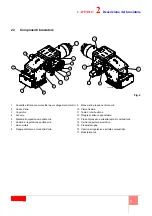
Page 7: ...5 Manometro pressione mandata olio 6 Camma di regolazione portata aria 7 Servomotore 8 Flangia di attacco al condotto d aria 9 Manometro pressione ritorno olio 10 Visore fiamma 11 Testa di combustion...

Page 8: ...Dimensioni di ingombro 372 514 1008 3 1 3 4 5 0 156 534 359 Fig 3 20110629 Collegamento canale aria Fig 4 D7549 DIMENSIONI FLANGE 4 54 5 453 M 18 350 D7884 6 5 5 1 8 5 4 54 5 1 4 5 M16 D7885 Alimentaz...

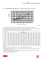
Page 9: ...0 200 220 250 0 0 920 0 988 1 055 1 122 1 190 1 257 1 325 1 392 1 459 1 527 1 594 1 662 1 763 100 0 932 1 000 1 069 1 137 1 205 1 273 1 342 1 410 1 478 1 547 1 615 1 683 1 786 500 0 976 1 047 1 119 1...

Page 10: ...perdita di carico della testa di combustione Gas naturale G 20 P C I 10 kWh Nm3 Le curve sono state ricavate nelle se guenti condizioni pressione misurata alla presa po sta sul pressostato a valle del...

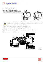
Page 11: ...presente manuale ed in conformit alle norme e disposizioni di legge vigenti 1 2 1 2 3 3 D12015 1 1 6 5 6 2 4 3 3 Fig 10 20110636 Togliere i perni d arresto 7 dell otturatore ed al loro posto montare l...

Page 12: ...e 6 Togliere il coperchio 7 Sganciare i collegamenti elettrici 8 e 9 di alta tensione dagli elettrodi del convogliatore e della testa 10 Svitare le viti 11 ed aprire il convogliatore 12 sulla cerniera...

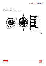
Page 13: ...11 CAPITOLO 3 Installazione 3 3 Posizione elettrodi Controllare che gli elettrodi siano posizionati come in Fig 12 A A 8 10mm 4 4 5mm Fig 12 D8665...

Page 14: ...el dado e controdado 4 NB Per una corretta taratura l eccentrico 1 deve lavorare su un campo di escursione del servomotore pi ampio possibile ad ogni variazione del servomotore deve corrispondere una...

Page 15: ...PG Regolatore bassa pressione gas MM Manometro PA Pressostato aria di minima PGM Pressostato gas di massima PGm Pressostato gas di minima RG Farfalla gas SRV Valvola limitatrice di pressione con scari...

Page 16: ...ig 15 La scelta del foro 1 2 3 da utilizzare si determina dal diagramma in Fig 16 in base alla potenza massima richiesta In fabbrica la regolazione viene predisposta per la corsa massima foro 3 Nel ca...

Page 17: ...commuta tori Camma pos 1 limita la massima apertura servomotore Camma pos 2 limita il fine corsa del servomotore sulla posi zione 0 A bruciatore spento la serranda dell aria risul ta completamente ch...

Page 18: ...il minimo A bruciatore spento la serranda dell aria risulta completamente chiusa 0 Camma III ARANCIO 20 Uguale per tutti i modelli Regola la posizione d accensione e potenza minima del combustibile 1...

Page 19: ...recchiatura 0 1 2 3 2 3 3 4 1 1 2 0 0 2 3 3 3 3 3 35 3 6 7 6 8 6 5 9 69 2 5 2 23 23 16 46 1 31 31 3 1 3 1 3 2 0 4 52 33 4 33 1 5 3 5 5 5 15 0 2 02 3 2 5 2 5 5 5 2 3 2 3 2 3 2 3 54 5 252 5 4 5 2 5 1 2...

Page 20: ...ore spento aprire le valvole manuali poste a monte della rampa gas regolare il pressostato gas di minima Fig 19 posto sulla rampa gas a inizio scala regolare il pressostato gas di massima Fig 20 posto...

Page 21: ...llo secondo Tab A e Tab B pag 20 Si consiglia di sostituire annualmente gli ugelli durante la manutenzione periodica L utilizzo di ugelli differenti da quelli pre scritti da Riello S p A e la non corr...

Page 22: ...B kg h Pressione mandata bar Pressione ritorno bar kg h kW 300 20 7 100 1200 20 17 5 257 3000 375 20 6 5 148 1750 20 15 5 305 3600 425 20 7 5 68 1950 20 17 5 365 4300 kg h Pressione mandata bar Press...

Page 23: ...entilazione il ser vomotore si fermer a circa 20 4 Regolare la pressione di mandata della pompa come evidenzia to nel punto a in modo da ottenere una pressione di mandata all ugello pari a 25 bar 5 Re...

Page 24: ...ato tutte le altre regolazioni del bruciatore con il pressostato gas di massima regolato a fine scala Fig 29 Con il bruciatore funzionante alla potenza massima diminuire la pressione di regola zione g...

Page 25: ...icare ed eventualmente pulire il dispositivo di accensione 3 Controllare il corretto valore delle pressioni del combustibile e dell aria 4 Verificare il corretto movimento e la taratura della serranda...

Page 26: ...mentazione delle valvole del gas potr essere veri ficata con l inserimento di un tester alcune valvole sono dotate di segnali luminosi o indicatori di posizione chiusura apertura che vengono attivati...

Page 27: ...apparecchiatura SMQ 10 servomotore SQM 10 Non interviene il contatto 2 del servomotore Regolare camma 2 o sostituire morsetti 11 8 apparecchiatura SMQ 40 servomotore SQM 40 Il bruciatore non si avvia...

Page 28: ...a in blocco con apparizione di fiamma Apparecchiatura elettrica difettosa Sostituirla Blocco senza indicazione di simbolo Simulazione di fiamma Sostituire apparecchiatura In funzionamento il bruciator...

Page 29: ...obina o pannello raddriz zatore Pressione gas troppo bassa Aumentarla al regolatore Trasformatore d accensione difettoso Sostituirlo Collegamenti elettrici valvole o trasformatore Rifarli d accensione...

Page 30: ...eguite con rete elettrica staccata PERICOLO 3 5 6 7 6 3 2 8 5 MB Morsettiera bruciatore PA Pressostato aria PGM Pressostato gas di massima PO Pressostato olio di minima SM Servomotore TA Trasformatore...

Page 31: ...ssostato aria PGM Pressostato gas di massima PO Pressostato olio di minima SM Servomotore TA Trasformatore di accensione XTB Terra bruciatore UV Sensore UV VF Valvola di funzionamento VR Valvola ritor...

Page 32: ...e for future consultation Who should receive it This handbook has been prepared for people who already have a working knowledge of all aspects involving oil and gas burners These aspects refer to inst...

Page 33: ...ion of electrodes 11 CHAPTER 4 Fuel supply 12 Pressure regulator 12 General gas supply layout example 13 CHAPTER 5 Preparation for start up 14 Combustion head adjustment 14 Servomotor adjustment SQM 1...

Page 34: ...cam Grandezza Series N fuel oil NS fuel oil natural gas NP fuel oil LPG NA fuel oil assisted atomisation L light oil TL long head Combustive air NAP fuel oil assisted atomisation LPG M progressive mod...

Page 35: ...iscosity 5 E at 50 C option L Natural gas G 20 PCI 10 kWh Nm3 option S Natural gas G 25 PCI 8 6 kWh Nm3 option S Combustive air temperature Max 250 C Electrical supply 230 V 10 50 60 Hz Ignition Direc...

Page 36: ...e 6 Air delivery adjustment cam 7 Servomotor 8 Air pipe attachment flange 9 Oil return pressure gauge 10 Flame inspection window 11 Combustion head 12 Boiler attachment 13 Combustion head air pressure...

Page 37: ...2 4 Overall dimensions 372 514 1008 3 1 3 4 5 0 156 534 359 Fig 3 20110629 Air duct connection Fig 4 D7549 FLANGE DIMENSIONS 4 54 5 453 M 18 350 D7884 6 5 5 1 8 5 4 54 5 1 4 5 M16 D7885 Gas supply Fi...

Page 38: ...0 0 988 1 055 1 122 1 190 1 257 1 325 1 392 1 459 1 527 1 594 1 662 1 763 100 0 932 1 000 1 069 1 137 1 205 1 273 1 342 1 410 1 478 1 547 1 615 1 683 1 786 500 0 976 1 047 1 119 1 190 1 262 1 333 1 40...

Page 39: ...Fig 8 It represents the pressure drop in the combustion head Natural gas G 20 Net calorific value 10 kWh Nm3 The curves were taken in the following conditions pressure measured at the test point on th...

Page 40: ...is manual and in compliance with the standards and regulations of the laws in force 1 2 1 2 3 3 D12015 Fig 10 Remove the stop pins 7 from the shutter and insert the supplied screws in their place Prep...

Page 41: ...e rods 3 and 4 by unscrewing the nuts 5 and 6 Remove cover 7 Disconnect the high voltage electrical connections 8 and 9 from the electrodes of the conveyor and head 10 Unscrew the screws 11 and open t...

Page 42: ...11 CHAPTER 3 Installation 3 3 Position of electrodes Make sure that the electrodes are positioned as shown in Fig 12 A A 8 10mm 4 4 5mm Fig 12 D8665...

Page 43: ...locknut 4 NB To obtain a correct calibration cam 1 must operate over the travel range of the servo motor as wider as possible every vari ation of the servo motor must be matched by a variation in pre...

Page 44: ...ressure regulator MM Pressure gauge PA Minimum air pressure switch PGM Maximum gas pressure switch PGm Minimum gas pressure switch RG Gas butterfly valve SRV Pressure limiting valve with outlet into t...

Page 45: ...hole 1 2 3 to be used is decided on the basis of diagram in Fig 16 against the required maximum output Setting is pre arranged in the plant for the maximum run hole 3 When dealing with boilers featur...

Page 46: ...tion the same number of selector switches Cam pos 1 limits maximum opening of the servomotor Cam pos 2 limits servomotor limit switch in the 0 position It is set in the factory at approx 20 just one t...

Page 47: ...rds the minimum With the burner off the air damper should be completely closed 0 Cam III ORANGE 20 The same for all models Adjusts the start up position and the mini mum output of the fuel 1 for singl...

Page 48: ...l box 0 1 2 3 2 3 3 4 1 1 2 0 0 2 3 3 3 3 3 35 3 6 7 6 8 6 5 9 69 2 5 2 23 23 16 46 1 31 31 3 1 3 1 3 2 0 4 52 33 4 33 1 5 3 5 5 5 15 0 2 02 3 2 5 2 5 5 5 2 3 2 3 2 3 2 3 54 5 252 5 4 5 2 5 1 2 5 5 3...

Page 49: ...n the manual valves upstream from the gas train adjust the minimum gas pressure switch Fig 19 on the gas train at the start of the scale adjust the maximum gas pressure switch Fig 20 on the butterfly...

Page 50: ...g to Tab A and Tab B page 20 It is advisable to replace nozzles every year during regular maintenance opera tions The use of nozzles other than those speci fied by Riello S p A and inadequate regular...

Page 51: ...B kg h Delivery pressure bar Return pressure bar kg h kW 300 20 7 100 1200 20 17 5 257 3000 375 20 6 5 148 1750 20 15 5 305 3600 425 20 7 5 68 1950 20 17 5 365 4300 kg h Delivery pressure bar Return...

Page 52: ...after the pre ventilation phase the servomotor will stop at approx 20 4 Adjust the pump delivery pressure as given in point a to obtain a delivery pressure of 25 bar 5 Adjust the return pressure to a...

Page 53: ...rmed all the other burner adjustments with the pressure switch set at the end of the scale Fig 29 With the burner operating at maximum output decrease adjustment pressure by slowly turning the relativ...

Page 54: ...e and check it is undamaged and clean 2 Check the ignition device and clean if necessary 3 Check the right pressure levels for fuel and air 4 Check the correct movement and setting of the air damper a...

Page 55: ...rical supply of the solenoid gas valves can be verified by inserting a tester Some valves are equipped with light signals or close open position indicator that turn on at the same time as their power...

Page 56: ...the control box do not operate SQM 40 servomotor SQM 40 The burner does not start and a function lock out occurs Flame simulation Replace control box The burner starts but stops at maximum air damper...

Page 57: ...ner goes to lock out right after flame appearance Defective control box Replace Lock out without symbol indica tion Flame simulation Replace control box During operation the burner stops in lock out F...

Page 58: ...ressure too low Increase on the regulator Defective ignition transformer Replace Erroneous valve or transformer electrical Repeat connections connections Defective control box Replace A cock down line...

Page 59: ...out with the electricity supply disconnected MB Burner terminal strip PA Air pressure switch PGM Max gas pressure switch PO Maximum oil pressure switch SM Servomotor TA Ignition transformer TB Burner...

Page 60: ...4 4 3 4 4 4 3 4 4 4 3 4 4 4 3 4 4 4 3 4 4 4 3 4 4 4 4 5 4 4 4 3 4 4 4 ASZ Servomotor potentiometer optional XT1 Burner terminal strip PA Air pressure switch PGM Max gas pressure switch PO Maximum oil...

Page 61: ...1...

Page 62: ...2 CHAPTER 1 3 3 3 CHAPTER 2 4 4 4 5 6 7 8 CHAPTER 3 9 9 10 11 CHAPTER 4 12 12 12 13 CHAPTER 5 14 14 SQM 10 15 SQM 40 16 SQM 40 17 18 19 CHAPTER 6 21 21 22 22 CHAPTER 7 23 23 23 25 CHAPTER 8 27...

Page 63: ...3 1 1 1 DB 6 LS TC A 0 A 0 A 90 TC S P LPG E N NS NP LPG NA L TL NAP LPG M LS LP LPG NAS TXL A 180 A 270 3 4 6 M DB 3 LSM TC A0 20147364 DB 4 LSM TC A0 20101590...

Page 64: ...00 2500 5000 kW 1 4 50 C 5 E L G 20 PCI 10 kWh Nm3 S G 25 PCI 8 6 kWh Nm3 S 250 C 230 V 10 50 60 Hz V1 V2 l1 l2 230V 2x5 kV 1 4 A 30 mA 24 FS1 50 C 150 C 250 C 0 500 2000 2850 3400 3800 kW DB3 DB4 kW...

Page 65: ...5 2 2 3 1 2 3 4 5 6 7 8 9 10 11 12 13 14 15 16 17 10 6 7 12 16 1 2 3 4 8 11 13 14 17 5 9 15 2 20110623...

Page 66: ...6 2 2 4 372 514 1008 3 1 3 4 5 0 156 534 359 3 20110629 Fig 4 D7549 4 54 5 453 M 18 350 D7884 6 5 5 1 8 5 4 54 5 1 4 5 M16 D7885 Fig 5 Fig 6...

Page 67: ...0 1 646 1 722 1 798 1 874 1 988 1250 1 069 1 147 1 226 1 304 1 382 1 460 1 539 1 617 1 695 1 774 1 852 1 930 2 048 1500 1 102 1 182 1 263 1 344 1 425 1 505 1 586 1 667 1 747 1 828 1 909 1 990 2 111 17...

Page 68: ...8 2 2 6 0 1000 2000 4000 6000 8000 60 50 40 30 20 10 m bar KW G 2 0 G 2 5 6 m bar KW 0 1000 2000 4000 6000 12 18 24 26 G 2 0 G 2 5 D8257 D8258 p mbar 8 G 20 10 kWh Nm3 0 mbar 9 Pb kW 8 p mbar Pb kW 9...

Page 69: ...9 3 3 1 1 2 3 M12 X 25 1 2 1 2 3 3 D12015 10 7 3 4 1 1 6 5 6 2 4 3 3 20110636...

Page 70: ...10 3 3 2 1 2 X1 5 6 3 4 7 10 8 9 11 12 10 13 14 10 X2 12 8 6 10 9 3 1 X1 7 11 5 4 2 11 20110641...

Page 71: ...11 3 3 3 12 A A 8 10mm 4 4 5mm 12 D8665...

Page 72: ...12 4 4 1 1 2 3 3 3 4 1 6 13 1 3 4 5 D8416 2 6...

Page 73: ...13 4 4 2 D7543 C GF HPG LPG MM PA PGM PGm RG SRV VE VPS VR VS 0 5 4 bar 500 mbar 14...

Page 74: ...14 5 5 1 7 2 1 2 3 15 1 2 3 16 3 16 16 15 D8419 N D7905 1600 2000 2400 2800 3200 3600 4000 4400 kW 4800 5200 3 2 1 0 5600 6000 kW...

Page 75: ...15 5 5 2 SQM 10 1 4 2 3 5 6 7 1 2 0 20 3 20 4 5 20 130 1 4 17 D1500...

Page 76: ...16 5 5 3 SQM 40 18 30 90 6 I 135 II 0 0 III 20 1 IV 130 1 V 20 2 VI 130 2 VI V IV III II I 0 8 0 0 3 5 1 L SQ M 40 SQ M4 1 R 9 0 6 0 6 0 9 0 3 0 13 5 0 0 R 20074577 18...

Page 77: ...0 2 3 3 3 3 3 35 3 6 7 6 8 6 5 9 69 2 5 2 23 23 16 46 1 31 31 3 1 3 1 3 2 0 4 52 33 4 33 1 5 3 5 5 5 15 0 2 02 3 2 5 2 5 5 5 2 3 2 3 2 3 2 3 54 5 252 5 4 5 2 5 1 2 5 5 3 5 3 8 1 0 1 81 2 1 81 2 1 2 3...

Page 78: ...18 5 5 5 19 20 21 D2213 D2215 19 20 21 D2214...

Page 79: ...19 5 5 6 EN 267 20 A B D3509 22 2...

Page 80: ...kW 300 20 7 100 1200 20 17 5 257 3000 375 20 6 5 148 1750 20 15 5 305 3600 425 20 7 5 68 1950 20 17 5 365 4300 kg h bar bar kg h kW 250 24 9 94 1120 25 15 5 210 2500 360 24 7 5 116 1380 25 14 260 309...

Page 81: ...21 6 6 1 a A 26 8 b 3 2 c 1 4 4 1 5 6 2 8 mm 8 mm 7 17 3 20 4 a 25 bar 5 4 bar 5 27 6 6 2 25 7 15 130 4 27 8 9 3 0 130 0 130 1 2 17 3 2 D1499 D1498 A D8416 5 4 1 6 27 25 26...

Page 82: ...22 6 6 2 28 20 CO 1 10 000 ppm CO 1 29 0 2 kPa 0 1 kPa 30 2 mbar 0 1 kPa 6 3 1 kPa 10 mbar 28 D2215 D3571 29 D3571 30...

Page 83: ...23 7 7 1 UV 70 A 187 V 100 A c c 100 F 1V c c 7 2 1 2 3 4 5 1 2 3 4 5 6 D1143 31...

Page 84: ...24 7 1 2 3 4 P 10 250 000 10 250 000 10 250 000 10 250 000 15 10 250 000 10 250 000 10 250 000 10 5 30 000 10 500 000...

Page 85: ...25 7 7 3 1 2 3 2 11 8 2 SQM 10 2 11 8 2 SQM 40 1 or 4 9 8 1 or 4 SQM 10 4 or 6 9 8 4 or 6 SQM 40 3 5 10 8 3 5 SQM 10 3 5 10 8 3 5 SQM 40...

Page 86: ...26 7 VR VR VS VR...

Page 87: ...27 8 SQM 10 MB PA PGM PO SM TA TB UV UV VF VR VRS VS 3 5 6 7 6 3 2 8 5...

Page 88: ...40 0 1 2 3 4 4 4 3 4 4 4 3 4 4 5 4 3 4 4 4 6 3 4 4 4 3 4 4 4 3 4 4 4 3 4 4 4 3 4 4 4 3 4 4 4 3 4 4 4 3 4 4 4 3 4 4 4 3 4 4 4 4 5 4 4 4 3 4 4 4 ASZ XT1 PA PGM PO SM TA XTB UV UV VF VR VRS VS X1 X2 X3...

Page 89: ......

Page 90: ......

Page 91: ......

Page 92: ...Con riserva di modifiche Subject to modifications RIELLO S p A I 37045 Legnago VR Tel 39 0442 630111 http www riello it http www riello com...

Reviews: