4
2
Burner description
2.1
Technical data
2.2
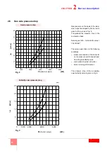
Firing rate
Model
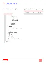
DB 3 LSM C13
DB 4 LSM C13
Capacity
Min./Max. light oil [kW]
500/2000 ÷ 3800
1000/2500 ÷ 5000
Min./Max. natural gas [kW]
Output adjustment
Modulating
Modulation ratio against
maximum rated output
Light oil
1 : 4
Fuel
Light oil/Fuel oil viscosity 5°E at 50°C
option L
Natural gas (G 20) - PCI 10 kWh/Nm
3
option S
Natural gas (G 25) - PCI 8,6 kWh/Nm
3
option S
Combustive air temperature
Max. 250°C
Electrical supply
230 V
+/-10%
50/60 Hz
Ignition
Directly
Ignition transformer
V1 - V2
l1 - l2
230V - 2x5 kV
1.4 A - 30 mA
Flame control
Standard (1 stop in 24 hours)
FS1
50°C
150°C
250°C
0
500
2000
2850 3400 3800
kW
DB3
DB4
kW
5000
4500
3750
2500
1000
0
50°C
150°C
250°C
Fig. 1
Air temperature
Burner output -
kW
D7667
Burner output -
kW
Ai
r te
mp
er
at
ure
Summary of Contents for DB 4 LSM C13
Page 2: ......
Page 61: ...1...
Page 69: ...9 3 3 1 1 2 3 M12 X 25 1 2 1 2 3 3 D12015 10 7 3 4 1 1 6 5 6 2 4 3 3 20110636...
Page 71: ...11 3 3 3 12 A A 8 10mm 4 4 5mm 12 D8665...
Page 72: ...12 4 4 1 1 2 3 3 3 4 1 6 13 1 3 4 5 D8416 2 6...
Page 73: ...13 4 4 2 D7543 C GF HPG LPG MM PA PGM PGm RG SRV VE VPS VR VS 0 5 4 bar 500 mbar 14...
Page 75: ...15 5 5 2 SQM 10 1 4 2 3 5 6 7 1 2 0 20 3 20 4 5 20 130 1 4 17 D1500...
Page 78: ...18 5 5 5 19 20 21 D2213 D2215 19 20 21 D2214...
Page 79: ...19 5 5 6 EN 267 20 A B D3509 22 2...
Page 83: ...23 7 7 1 UV 70 A 187 V 100 A c c 100 F 1V c c 7 2 1 2 3 4 5 1 2 3 4 5 6 D1143 31...
Page 86: ...26 7 VR VR VS VR...
Page 87: ...27 8 SQM 10 MB PA PGM PO SM TA TB UV UV VF VR VRS VS 3 5 6 7 6 3 2 8 5...
Page 89: ......
Page 90: ......
Page 91: ......


