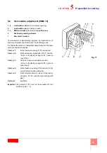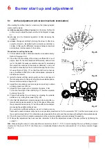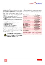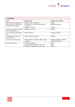
28
8
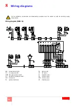
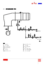
Wiring diagrams
Wiring diagram (SQM 10)
All the installation, maintenance and disassembly operations must be carried out with the electricity supply
disconnected.
MB
Burner terminal strip
PA
Air pressure switch
PGM Max. gas pressure switch
PO
Maximum oil pressure switch
SM
Servomotor
TA
Ignition transformer
TB
Burner earth
UV
UV sensor
VF
Operation valve
VR
Oil return valve
VRS
Oil return valve
VS
Oil safety valve
#
%
/#
/
###3(
5
/
#
6
/#
#
#
#
7
#
#
#
#
#
6
#
#
#
/
#
%
%
#
%
/
#
%
#
%
#
%
#
%
#
%
#
%
/
#
%
#
#
%
#
%
/#
/
#
%
#
%
#
%
3
/#
%
#
%
/
#
/#
2
8
>'<!
>'&-5
;)!?
Summary of Contents for DB 4 LSM C13
Page 2: ......
Page 61: ...1...
Page 69: ...9 3 3 1 1 2 3 M12 X 25 1 2 1 2 3 3 D12015 10 7 3 4 1 1 6 5 6 2 4 3 3 20110636...
Page 71: ...11 3 3 3 12 A A 8 10mm 4 4 5mm 12 D8665...
Page 72: ...12 4 4 1 1 2 3 3 3 4 1 6 13 1 3 4 5 D8416 2 6...
Page 73: ...13 4 4 2 D7543 C GF HPG LPG MM PA PGM PGm RG SRV VE VPS VR VS 0 5 4 bar 500 mbar 14...
Page 75: ...15 5 5 2 SQM 10 1 4 2 3 5 6 7 1 2 0 20 3 20 4 5 20 130 1 4 17 D1500...
Page 78: ...18 5 5 5 19 20 21 D2213 D2215 19 20 21 D2214...
Page 79: ...19 5 5 6 EN 267 20 A B D3509 22 2...
Page 83: ...23 7 7 1 UV 70 A 187 V 100 A c c 100 F 1V c c 7 2 1 2 3 4 5 1 2 3 4 5 6 D1143 31...
Page 86: ...26 7 VR VR VS VR...
Page 87: ...27 8 SQM 10 MB PA PGM PO SM TA TB UV UV VF VR VRS VS 3 5 6 7 6 3 2 8 5...
Page 89: ......
Page 90: ......
Page 91: ......


