11
CHAPTER
4
Fuel supply
4.2
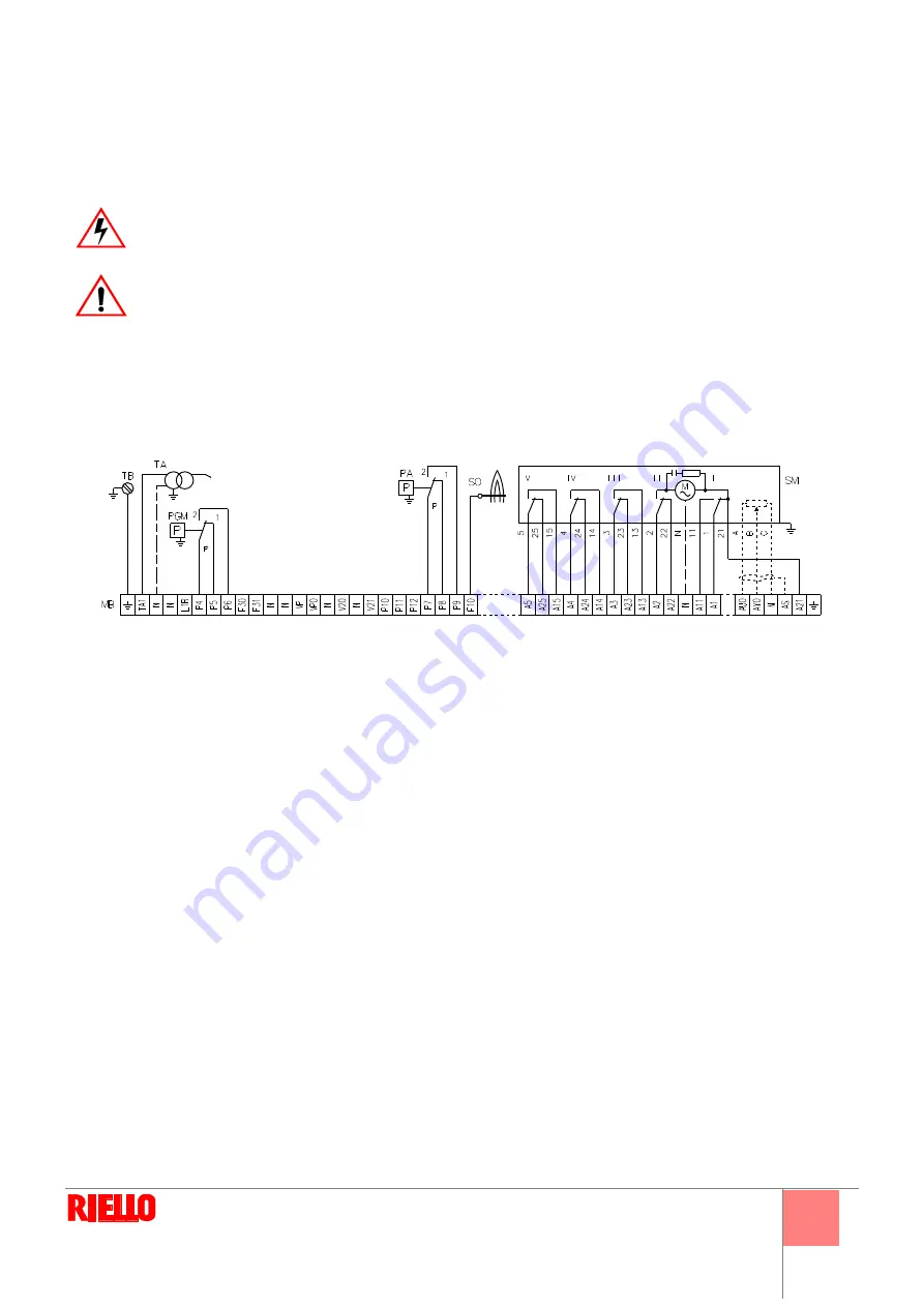
Wiring diagrams
All the installation, maintenance and disassembly operations must be carried out with the electricity supply disconnected.
The installation of the burner must be carried out by qualified personnel, as indicated in this manual and in compliance with the
standards and regulations of the laws in force.
DANGER
WARNING
MB
Burner terminal strip
PA
Air pressure switch
PGM
Maximum gas pressure switch
SM
Servomotor
SO
Ionisation probe
TA
Ignition transformer
TB
Burner earth
D7904
Fig. 13
Summary of Contents for DB 4 SM BLU
Page 2: ......
Page 39: ...1...
Page 48: ...10 4 4 1 D7543 C GF HPG LPG MM PA PGM PGm RG SRV VE VPS VR VS 0 5 4 bar 500 mbar 12...
Page 49: ...11 4 4 2 DANGER WARNING MB PA PGM SM SO TA TB D7904 13...
Page 51: ...13 5 5 3 1 4 2 3 5 6 7 1 2 0 3 20 4 5 20 130 1 4 5 4 130 19 18 D1500 3 2 4 1 19 1 2 3 4 D1499...
Page 52: ...14 5 MAN 3 1 130 90 2 19 2 19 20 2 2...
Page 54: ...16 5 5 7 6 A 100 A 5 8 1 2 3 4 5 1 2 3 4 5 6 D3097 23 A...
Page 55: ...17 6 6 1 1 2 3 VR VR VS VR WARNING DANGER...
Page 56: ...18 6...
Page 57: ......
Page 58: ......
Page 59: ......


