13
CHAPTER
5
Preparation for start up
5.3
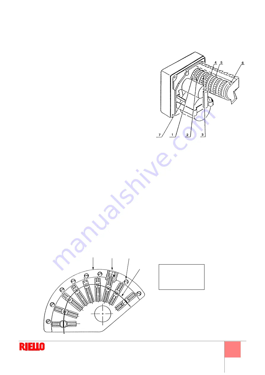
Servomotor adjustment
1 - 4
:
Limit switch cam
(max. air damper opening)
2
:
Limit switch cam
(air damper closed)
3 - 5
:
Minimum delivery
(and ignition)
position cam
6
:
Positioning reading indicator
7
:
Servomotor release
The servomotor contemporarily regulates, by transmission, air delivery
and pressure and delivery of the fuel being used.
It is fitted with a number of adjustable cams that action the same
number of selector switches.
Cam
pos.
1
:
limits maximum opening of the servomotor.
Cam
pos.
2
:
limits servomotor limit switch in the 0° position.
When the burner is off, the air damper is completely
closed.
Cam
pos.
3
:
fixes the minimum modulation position.
It is set in the factory at approx. 20° (just one type of fuel).
Cam
pos.
4
:
limits maximum opening of the servomotor (for mixed burners working with gas).
Cam
pos.
5
:
limits minimum delivery. It is set in the factory at approx. 20° (for mixed burners working with gas).
Cam
rest
:
available.
Important
: the position of 130° must not be exceeded for limit switches (cam 1 - 4).
5.4
Air/fuel adjustment
Fuel/combustion air is synchronized by means of a servomotor that, connected to a variable-profile cam, operates the outlet air
dampers and, by means of suitable linkage, the combustion head and gas butterfly valve.
To reduce pressure loss and to have a wider adjustment range, it is best to set the servomotor to the maximum output used, as
near to maximum opening (130°) as possible.
On the gas butterfly valve, the fuel’s partial setting adjustment based on required output, with the servomotor fully open, is made
by using the pressure stabilizer on the train.
When setting the air/fuel ratio for the gas burners, the air and gas variable profile cams must be used, Fig. 19.
Fig. 18
D1500
3
2
4
1
Fig. 19
1
Cam
2
Adjustment screws
3
Fixing screws
4
Variable profile
D1499
Summary of Contents for DB 4 SM BLU
Page 2: ......
Page 39: ...1...
Page 48: ...10 4 4 1 D7543 C GF HPG LPG MM PA PGM PGm RG SRV VE VPS VR VS 0 5 4 bar 500 mbar 12...
Page 49: ...11 4 4 2 DANGER WARNING MB PA PGM SM SO TA TB D7904 13...
Page 51: ...13 5 5 3 1 4 2 3 5 6 7 1 2 0 3 20 4 5 20 130 1 4 5 4 130 19 18 D1500 3 2 4 1 19 1 2 3 4 D1499...
Page 52: ...14 5 MAN 3 1 130 90 2 19 2 19 20 2 2...
Page 54: ...16 5 5 7 6 A 100 A 5 8 1 2 3 4 5 1 2 3 4 5 6 D3097 23 A...
Page 55: ...17 6 6 1 1 2 3 VR VR VS VR WARNING DANGER...
Page 56: ...18 6...
Page 57: ......
Page 58: ......
Page 59: ......


