background image

18

7

Manutenzione

7.1

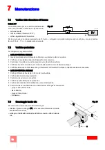
Verifica della rilevazione di fiamma

Cellula UV

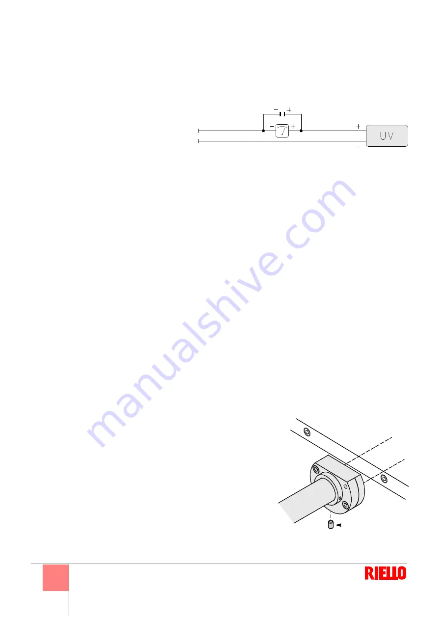
La corrente minima per un corretto funzionamento è
di 70 µA. Se il valore è inferiore può dipendere da:
• cellula esaurita;
• tensione bassa (inferiore a 187 V);
• cattiva regolazione del bruciatore.
Per la misura usare un microamperometro da 100 µA c.c., collegato in serie alla cellula, secondo lo schema, con un condensa

-

tore da 100 µF - 1V c.c. in parallelo allo strumento.

7.2

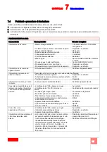
Verifiche periodiche

Si consigliano le seguenti verifiche:

y

LISTA DI VERIFICA MENSILE

1 Ispezionare il dispositivo di rilevazione fiamma e verificarne lo stato e la pulizia.
2 Verificare ed eventualmente pulire il dispositivo di accensione.
3 Controllare il corretto valore delle pressioni del combustibile e dell’aria.
4 Verificare il corretto movimento e la taratura della serranda aria e dei levismi collegati.
5 Verificare la sequenza di avviamento e gli interblocchi di sicurezza simulando la relativa condizione di anomalia.

y

LISTA DI VERIFICA ANNUALE

1 Verifica di tenuta delle valvole di blocco del combustibile.
2 Verifica delle tarature dei pressostati.
3 Controllo visivo dei cavi e connettori.
4 Verifica e pulizia delle prese di pressione.
5 Verifica delle tubazioni dell’installazione per eventuali perdite.
6 Controllo visivo di eventuali danni e/o deformazioni dei seguenti componenti:

- gruppo cilindro/distributore;
- disco fiamma;
- gruppo di accensione;
- tubi fiamma

.

7.3

Smontaggio lancia olio

Per rimuovere la lancia olio procedere come segue:
• allentare il grano di serraggio (A) posto sulla zona inferiore del morsetto 

fissato alla cassa d’aria;

• scollegare i tubi flessibili dalla parte dell’attacco rapido e sfilare la lancia 

olio.

D1143

Fig. 27

D2158

A

Fig. 28

Summary of Contents for DB9 LSE C13 TC FS1 A0

Page 1: ...enance instructions 安装 使用和维护手册 20074523 2 03 2014 Bruciatore policombustibile gasolio gas Dual fuel gas oil gas burner 燃油 燃气双燃料燃烧器 Funzionamento modulante Modulating operation 电子比例调节运行 CODICE CODE 代码 MODELLO MODEL 型号 TIPO TYPE 类型 20074416 DB9 LSE C13 TC FS1 A0 74416X I GB CN ...

Page 2: ......

Page 3: ...ltazione Destinatari Questo manuale è stato realizzato per un utilizzo da parte di personale che ha già familiarità con tutti gli aspetti connessi a bruciatori ad olio e a gas Questi aspetti sono inerenti a installazione uso manutenzione sicurezza Per i destinatari di tale manuale si presume inoltre una qualifica ta ed un adeguata esperienza su questo tipo di apparecchi e sul loro tipico ambiente ...

Page 4: ...e 11 4 1 Collegamento alimentazione gas al bruciatore 11 4 2 Schema generale di alimentazione 12 CAPITOLO 5 Preparazione all avviamento 13 5 1 Regolazione della testa di combustione 13 5 2 Pilota di accensione 13 5 3 Regolazione pressostati 14 5 4 Lancia portaugello 15 CAPITOLO 6 Avviamento e regolazione bruciatore 16 6 1 Sistema di regolazione aria combustibile e modulazione di potenza 16 6 2 Tar...

Page 5: ...ronica Grandezza Serie N olio combustibile NS olio combustibile gas naturale NP olio combustibile GPL NA olio combustibile atom assistita L gasolio TL testa lunga Alimentazione aria NAP olio comb atom assistita GPL M progressivo modulante camma meccanica LS gasolio gas naturale LP gasolio GPL NAS olio comb atom assistita gas naturale TXL testa speciale A 180 dall alto A 270 da sinistra 9 12 E TIPO...

Page 6: ...0 PCI 10 kWh Nm3 opzione S Gas naturale G 25 PCI 8 6 kWh Nm3 opzione S Gasolio Olio combustibile fluido viscosità fino 5 E a 50 C opzione L Temperatura aria comburente Max 150 C Alimentazione elettrica 400 V 10 50 Hz Accensione Tipo elettrogas bruciatore pilota a gas naturale Trasformatore di accensione V1 V2 l1 l2 230 V 1 x 8 kV 1 4 A 30 mA Controllo fiamma Standard 1 arresto ogni 24 ore FS1 G AS...

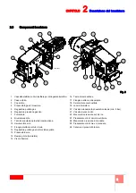
Page 7: ... aria 11 Flangia di attacco ai tubi d aria 12 Regolatore portata gas del bruciatore pilota 13 Pressostato aria 14 Rampa pilota bruciatore 15 Visore fiamma 16 Testa di combustione 17 Flangia di attacco alla caldaia 18 Servomotore combustibile 19 Lancia bruciatore 20 Valvola azionamento pneumatico lancia min 5 bar 21 Valvola sicurezza olio 22 Manometro pressione sul ritorno 23 Pressostato olio di mi...

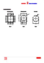
Page 8: ...atore 430 4 3 0 420 DB 9 470 DB 12 M 18 Collegamento canale aria D3972 D3973 Fig 3 Fig 4 D3974 Fig 5 DIMENSIONI FLANGE Fissaggio alla caldaia Alimentazione gas 400 470 11 4 3 6 5 0 6 2 0 0 2 0 0 2 3 8 2 3 8 180 180 220 220 DN 80 160 18 ...

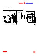
Page 9: ...7 CAPITOLO 2 Descrizione del bruciatore 2 4 Dimensioni di ingombro Fig 6 20075188 ...

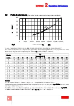
Page 10: ... 120 140 150 0 0 920 0 988 1 021 1 055 1 089 1 122 1 156 1 190 1 223 1 257 1 325 1 392 1 426 100 0 932 1 000 1 034 1 069 1 103 1 137 1 171 1 205 1 239 1 273 1 342 1 410 1 444 500 0 976 1 047 1 083 1 119 1 155 1 190 1 226 1 262 1 298 1 333 1 405 1 477 1 512 750 1 007 1 080 1 117 1 154 1 191 1 228 1 265 1 302 1 338 1 375 1 449 1 523 1 560 1000 1 038 1 114 1 152 1 190 1 228 1 266 1 304 1 342 1 380 1 ...

Page 11: ...la perdita di carico della testa di combustione Gas naturale G 20 P C I 10 kWh Nm3 Le curve sono state ricavate nelle seguenti condizioni pressione misurata alla presa posta sul pressostato a valle della farfalla gas camera di combustione a 0 mbar bruciatore funzionante a pie na potenza La perdita di pressione della val vola a farfalla totalmente aperta è riportata in Fig 9 D3978 D3979 Perdite tes...

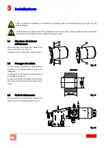
Page 12: ... in refrattario non deve esten dersi oltre la fine della testa di combustione del bru ciatore 3 3 Punti di sollevamento Per movimentare il bruciatore si raccomanda di uti lizzare solo i punti di attacco riportati in Fig 12 Tutte le operazioni di installazione manutenzione e smontaggio devono assolutamente essere eseguite con rete elettrica staccata L installazione del bruciatore deve essere effett...

Page 13: ...ollegare la flangia gas alla rampa utilizzare gli appositi adattatori previsti come accessori Collegamento del bruciatore pilota Il bruciatore è dotato di una rampa gas dedicata che si trova fissata sopra il manicotto Effettuare il collegamento sulla rampa principale a valle del filtro o del regolatore di pressione secondo configurazione Nei disegni sottostanti viene riportata la versione per alim...

Page 14: ...io LPG Regolatore bassa pressione gas MM Manometro MN Manometro mandata olio MR Manometro ritorno olio N Ugello NL Lancia olio PA Pressostato aria di minima PCV Regolatore pressione gas pilota PGM Pressostato gas di massima PGm Pressostato gas di minima PO Pressostato olio di massima RG Farfalla gas RP Regolatore pressione ritorno olio SM Servomotore SRV Valvola limitatrice di pressione con scaric...

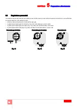
Page 15: ...otore l aria non sia sufficiente a garantire la massima potenza desiderata spostare il tirante 4 sul foro successivo numericamente più alto aumentando così l apertura della testa e quindi la portata d aria Lo spostamento del tirante 4 sui vari fori di fulcro fa variare l apertura massima della testa alla rotazione di 90 del servomotore mentre mantiene inalterata l apertura minima alla posizione 0 ...

Page 16: ...tore spento aprire le valvole manuali poste a monte della rampa gas regolare il pressostato gas di minima Fig 18 posto sulla rampa gas a inizio scala regolare il pressostato gas di massima Fig 19 posto sulla valvola a farfalla a fine scala regolare il pressostato aria Fig 20 posto sulla cassa d aria del bruciatore a inizio scala D2214 D2213 D2215 Pressostato gas di minima Pressostato gas di massim...

Page 17: ...po W2 Gamma completa ugelli Bergonzo B5 45 450 500 550 600 650 700 750 800 Fluidics W2 50 450 500 550 600 650 700 750 800 Per portate intermedie scegliere l ugello con portata nominale leggermente superiore a quella effettivamente richiesta Sono normalmente consigliati angoli di polverizzazione di 45 60 per camere di combustione strette usare ugelli con angoli di 30 35 ARI A AI R 1 3 4 2 5 D9926 F...

Page 18: ...caldaia ai valori di esercizio impostati 3 la correzione fine in continuo della portata d aria in funzione dell analisi dei fumi effettuata al camino O2 tale funzione è as sociata alla presenza del Kit O2 contenente il modulo PLL e il sensore QGO2 4 la misura del rendimento di combustione tale funzione è associata alla presenza del Kit O2 5 la sequenza regolazione in cascata di più caldaie tramite...

Page 19: ...e scala Fig 25 Con il bruciatore funzionante alla potenza MAX diminuire la pressione di regolazio ne girando lentamente in senso antiorario la manopolina di regolazione fino al blocco del bruciatore Girare quindi in senso orario la manopolina di 2 mbar e ripetere l avviamento del bruciatore Se il bruciatore si blocca nuovamente girare ancora in senso orario di 1 mbar Pressostato gas di minima Eseg...

Page 20: ...aria 4 Verificare il corretto movimento e la taratura della serranda aria e dei levismi collegati 5 Verificare la sequenza di avviamento e gli interblocchi di sicurezza simulando la relativa condizione di anomalia y LISTA DI VERIFICA ANNUALE 1 Verifica di tenuta delle valvole di blocco del combustibile 2 Verifica delle tarature dei pressostati 3 Controllo visivo dei cavi e connettori 4 Verifica e ...

Page 21: ...o o sostituirlo Tubetto presa pressione del pressostato ostruito Pulirlo Testa mal regolata Regolarla Il bruciatore si avvia e poi resta in blocco Avaria al circuito rivelazione fiamma Sostituire apparecchiatura Superata la preventilazione ed il tempo di sicurezza il bruciatore va in blocco senza apparizione fiamma L elettrovalvola VR fa passare poco gas Aumentarlo L elettrovalvola VR o VS non si ...

Page 22: ...di fiamma Sostituire l apparecchiatura Il bruciatore si avvia e poi si arresta in blocco Pressostato aria non commuta per pressione aria insufficiente Pressostato aria mal regolato Regolarlo o sostituirlo Tubetto presa pressione del pressostato ostruito Pulirlo Testa mal regolata Regolarla Il bruciatore si avvia e poi resta in blocco Avaria al circuito rivelazione fiamma Sostituire apparecchiatura...

Page 23: ...ace for future consultation Who should receive it This handbook has been prepared for people who already have a working knowledge of all aspects involving oil and gas burners These aspects refer to installation use maintenance safety Those who receive the handbook should also have qualified and sufficient experience in this sort of appliance and typical working environments Relative documentation ...

Page 24: ...APTER 4 Fuel supply 11 4 1 Gas supply connections to the burner 11 4 2 General supply layout 12 CHAPTER 5 Preparation for start up 13 5 1 Combustion head adjustment 13 5 2 Ignition pilot 13 5 3 Pressure switches adjustment 14 5 4 Nozzle holder lance 15 CHAPTER 6 Burner start up and adjustment 16 6 1 Air fuel control and power modulation system 16 6 2 Pressure switches setting 17 6 3 Final checks 1...

Page 25: ... electronic cam Grandezza Series N fuel oil NS fuel oil natural gas NP fuel oil LPG NA fuel oil assisted atomisation L light oil TL long head Combustive air NAP fuel oil assisted atomisation LPG M progressive modulating mechanical cam LS light oil natural gas LP light oil LPG NAS fuel oil assisted atomisation natural gas TXL special head A 180 from above A 270 from the left 9 12 E TYPE CODE DB9 LS...

Page 26: ... Natural gas G 20 PCI 10 kWh Nm3 option S Natural gas G 25 PCI 8 6 kWh Nm3 option S Light oil Fuel oil viscosity 5 E at 50 C option L Combustive air temperature Max 150 C Electrical supply 400 V 10 50 Hz Ignition Electrogas type pilot burner with natural gas Ignition transformer V1 V2 l1 l2 230 V 1 x 8 kV 1 4 A 30 mA Flame control Standard 1 stop in 24 hours FS1 G AS 0 50 C 150 C 2000 5500 kW Ai r...

Page 27: ...0 Air servomotor 11 Air pipe attachment flange 12 Gas delivery regulator pilot burner 13 Air pressure switch 14 Gas train pilot burner 15 Flame inspection window 16 Combustion head 17 Boiler attachment flange 18 Fuel servomotor 19 Burner lance 20 Lance pneumatic activation valve 5 bars min 21 Safety oil valve 22 Pressure gauge return 23 Minumum oil pressure switch on return 24 Pressure gauge deliv...

Page 28: ...cription Air duct connection D3972 D3973 Fig 3 Fig 4 D3974 Fig 5 FLANGE DIMENSIONS Fixing to the boiler Gas supply 400 470 11 4 3 6 5 0 6 2 0 0 2 0 0 2 3 8 2 3 8 180 180 220 220 DN 80 160 18 430 4 3 0 420 DB 9 470 DB 12 M 18 ...

Page 29: ...7 CHAPTER 2 Burner description 2 4 Overall dimensions Fig 6 20075188 ...

Page 30: ...0 988 1 021 1 055 1 089 1 122 1 156 1 190 1 223 1 257 1 325 1 392 1 426 100 0 932 1 000 1 034 1 069 1 103 1 137 1 171 1 205 1 239 1 273 1 342 1 410 1 444 500 0 976 1 047 1 083 1 119 1 155 1 190 1 226 1 262 1 298 1 333 1 405 1 477 1 512 750 1 007 1 080 1 117 1 154 1 191 1 228 1 265 1 302 1 338 1 375 1 449 1 523 1 560 1000 1 038 1 114 1 152 1 190 1 228 1 266 1 304 1 342 1 380 1 418 1 494 1 570 1 608...

Page 31: ... the pressure drop in the combustion head Natural gas G 20 Net calorific value 10 kWh Nm3 The curves were taken in the fol lowing conditions pressure measured at the test point on the pressure switch downstream from the gas but terfly valve combustion chamber at 0 mbar burner working at full output The pressure drop of the com pletely open butterfly valve is given in Fig 9 D3978 D3979 Head pressur...

Page 32: ...ase the fettled wall should not extend be yond the end of the burner combustion head 3 3 Lifting points To move the burner the attachment points indicat ed in Fig 12 should be used All the installation maintenance and disassembly operations must be carried out with the electricity supply disconnected The installation of the burner must be carried out by qualified personnel as indicated in this man...

Page 33: ...ve 5 Fig 2 The size of the flange is given in page 6 Use the relative adapters to connect the gas flange to the train supplied as accessories Pilot burner connection The burner has a special gas train that is fixed over the manifold It should be connected to the main train downstream from the filter or pressure regulator depending on the configuration The diagrams below show the natural gas versio...

Page 34: ... pressure regulator MM Pressure gauge MN Oil delivery pressure gauge MR Oil return pressure gauge N Nozzle NL Oil lance PA Minimum air pressure switch PCV Gas pressure regulator PGM Maximum gas pressure switch PGm Minimum gas pressure switch PO Maximum oil pressure switch RG Gas butterfly valve RP Oil return pressure regulator SM Servomotor SRV Pressure limiting valve with outlet into the environm...

Page 35: ...tor the air is insufficient to guarantee the maximum required output move the tie rod 4 to the following numerically higher hole thus increasing head opening and therefore air delivery Moving tie rod 4 onto the different fulcrum holes varies the head s maximum opening when the servomotor turns 90 whilst minimum opening when the servomotor is in the 0 position remains unchanged 5 2 Ignition pilot F...

Page 36: ...en the manual valves upstream from the gas train adjust the minimum gas pressure switch Fig 18 on the gas train at the start of the scale adjust the maximum gas pressure switch Fig 19 on the butterfly valve at the end of the scale adjust the air pressure switch Fig 20 on the burner air box at the start of the scale D2214 D2213 D2215 Minimum gas pressure switch Maximum gas pressure switch Air press...

Page 37: ...UIDICS type W2 Complete range of nozzles Bergonzo B5 45 450 500 550 600 650 700 750 800 Fluidics W2 50 450 500 550 600 650 700 750 800 For intermediate delivery levels choose the nozzle with delivery slightly higher than that effectively required Normally atomisation angles are recommended of 45 60 for narrow combustion chambers use nozzles with 30 35 angles ARI A AI R 1 3 4 2 5 D9926 Fig 21 Fig 2...

Page 38: ...re or temperature of the boiler at the working values set 3 the fine continuous adjustment of the air flow rate according to the gas analysis made at the flue O2 this function requires the O2 kit containing the PLL module and the QGO2 sensor 4 the measurement of the combustion yield this function requires the O2 kit 5 the sequence cascade adjustment of several boilers suitably connected Further in...

Page 39: ...et to the end of the scale Fig 25 With the burner operating at MAX output reduce the adjustment pressure by slowly turning the adjustment knob anticlockwise until the burner locks out Then turn the knob clock wise by 2 mbar and repeat burner firing If the burner locks out again turn the knob again clockwise by 1 mbar Minimum gas pressure switch Adjust the minimum gas pressure switch after having p...

Page 40: ... for fuel and air 4 Check the correct movement and setting of the air damper and relative lifting assemblies 5 Check the start up sequence and the safety interlocks by simulating the relative anomaly situation y LIST OF YEARLY CHECKS 1 Check the fuel blocking valves are still well sealed 2 Check the settings on the pressure switches 3 Visual check of the wires and connectors 4 Check and clean the ...

Page 41: ...sure point pipe blocked Clean is blocked Head wrong adjusted Adjust The burner starts and then locks out Fault in flame detection circuit Replace flame control After pre purge and safety time the burner goes to lock out and the flame does not appear The solenoid VR allows little gas through Increase Solenoid valves VR or VS fail to open Renew the coil or rectifier panel Gas pressure too low Increa...

Page 42: ...s Flame simulation Replace control box The burner ignites but then blocks Air pressure switch inoperative due to insufficient air pressure Air pressure switch adjusted badly Adjust or replace Pressure switch pressure point pipe blocked Clean is blocked Head wrong adjusted Adjust The burner starts and then locks out Fault in flame detection circuit Replace flame control After pre purge and safety t...

Page 43: ...1 一般提示 关于本手册 本手册与燃烧器随机附带 安装 使用和维护燃烧器前须认真 阅读 并妥善保管以备查阅 手册使用者 本手册提供给具有燃油及燃气燃烧器工作经验的有关人员 本手册包括下列相关信息 安装 使用 维护 安全注意事项 本手册的使用人员必须具有操作这类燃烧器的资质及丰富的现 场工作经验 相关文件 燃气阀组 控制面板接线图 负荷调节器 比例调节 ...

Page 44: ...力损失 8 2 6 燃气侧压力损失 9 第 3 安装 10 3 2 固定到锅炉 10 3 3 起吊点 10 第 4 燃料供给 11 4 1 连接到燃烧器的燃气供应 11 4 2 燃气总供给示意图 12 第 5 燃烧器启动准备 13 5 1 燃烧头调节 13 5 2 点火测试 13 5 3 压力开关调节 14 5 4 喷嘴支架 15 第 6 燃烧器启动及调节 16 6 1 空气 燃料控制及出力比调系统 16 6 2 压力开关设定 17 6 3 最终检查 17 第 7 维护 18 7 1 检查火焰探测器 18 7 2 定期检查 18 7 3 油枪拆卸 18 7 4 问题及解决方案 19 8 附录 控制面板示意图 21 ...

Page 45: ... 0 从底部 A 90 从右侧 燃烧头 TC 标准 燃料 S 天然气 P LPG 调节 E 电子比调 大小 系列 N 重油 NS 重油 天然气 NP 重油 LPG NA 介质雾化重油 L 轻油 TL 加长 助燃空气进风位置 NAP 介质雾化重油 LPG M 机械比调 比调 机械凸轮 LS 轻油 天然气 LP 轻油 LPG NAS 介质雾化重油 天然气 TXL 特制 A 180 从上部 A 270 从左侧 9 12 E 类型 代码 DB9 LSE C13 TC FS1 A0 20074416 ...

Page 46: ...调节比 天然气 1 6 轻油 1 4 燃料 天然气 G 20 PCI 10 kWh Nm3 选项 S 天然气 G 25 PCI 8 6 kWh Nm3 选项 S 轻油 燃油粘度为 50 C 时 5 E 选项 L 助燃空气温度 最高 150 C 电源 400 V 10 50 Hz 点火 点火枪 点火枪使用天然气或 LPG 点火变压器 V1 V2 l1 l2 230 V 1 x 8 kV 1 4 A 30 mA 火焰控制 标准 每 24 小时停机一次 FS1 G AS 0 50 C 150 C 2000 5500 kW Ai r t em per at ur e DB9 8600 9500 250 C 7150 图 1 D3976 空气温度 ...

Page 47: ...力开关 5 油压调节器 6 燃气阀组连接法兰 7 火焰检测器 8 点火枪 9 燃烧头调节控制杆 10 空气伺服马达 11 风管连接法兰 12 点火枪燃气压力调节器 13 风压开关 14 点火枪燃气阀组 燃烧器 15 火焰检查窗 16 燃烧头 17 锅炉连接法兰 18 燃料伺服马达 19 燃烧器油枪 20 油枪气动阀 最小压力为 5 bars 21 燃油安全阀 22 燃料回路压力表 23 回路上的最小油压开关 24 燃料输出压力表 25 最大输出油压开关 26 油枪位置传感器 20075187 图 2 ...

Page 48: ...6 第 2 章 燃烧器描述 风管连接法兰 D3972 D3973 图 3 图 4 D3974 图 5 法兰尺寸 锅炉连接法兰 燃气管路连接法兰 400 470 11 4 3 6 5 0 6 2 0 0 2 0 0 2 3 8 2 3 8 180 180 220 220 DN 80 160 18 430 4 3 0 420 DB 9 470 DB 12 M 18 ...

Page 49: ...7 第 2 章 燃烧器描述 2 4 外观尺寸 图 6 20075188 ...

Page 50: ...54 1 191 1 228 1 265 1 302 1 338 1 375 1 449 1 523 1 560 1000 1 038 1 114 1 152 1 190 1 228 1 266 1 304 1 342 1 380 1 418 1 494 1 570 1 608 1250 1 069 1 147 1 186 1 226 1 265 1 304 1 343 1 382 1 421 1 460 1 539 1 617 1 656 1500 1 102 1 182 1 223 1 263 1 304 1 344 1 384 1 425 1 465 1 505 1 586 1 667 1 707 1750 1 130 1 213 1 254 1 295 1 337 1 378 1 419 1 461 1 502 1 544 1 626 1 709 1 751 2000 1 174 ...

Page 51: ...10000 12000 14000 m bar KW D B 9 D B 1 2 m bar KW 18 16 14 12 10 8 6 4 2 燃烧器满负荷时 其燃气压力为 图 8 中给出曲线 该曲线代表了燃烧头的压力损 失 天然气 G 20 净热值 10 kWh Nm3 该曲线在以下条件下得出 燃气蝶阀下游的压力开关处 压力测试点的压力 炉膛压力为 0 mbar 燃烧器满负荷运行 蝶阀全开时的压力损失如图 9 D3978 D3979 燃烧头压力损失 Pb 燃烧器出力 kW 图 8 图 9 蝶阀压力损失 Pb 燃烧器出力 kW p mbar p mbar ...

Page 52: ... M12 X 25 替代 3 2 固定燃烧器到锅炉 图11显示如何将燃烧器固定到不带前冷却板的锅炉 上 燃烧头突出锅炉前板的长度不应超过 200 mm 任何情况下 燃烧筒长度都必须大于锅炉炉门加装 炉衬后的总厚度 3 3 起吊点 移动燃烧器时 应使用图 12 中标出的起吊点 危险 所有安装 维护和拆卸操作都必须在断开电源后进行 警告 安装燃烧器必须由有资质的人员进行操作 且符合安装地的强制标准 1 2 1 2 3 3 D12015 图 10 D2129 图 11 炉补 最大 500 ø 416 ø 430 图 12 20075189 ...

Page 53: ...11 4 燃料供应 4 1 连接到燃烧器的燃气供应 燃气供应压力 50 500 mbar 图 14 燃烧器连接 燃烧器通过燃气蝶阀上的法兰 5 图 2 与燃气阀组连接 法兰尺寸见第 6 页 使用随附的相关适配器来连接燃气法兰和阀组 点火枪连接 燃烧器有一个固定在多歧管上的点火枪燃气阀组 此燃气阀组应连接到过滤器或调压器 视不同配置而定 下游的主阀组上 下图为使用天然气为燃料的燃烧器示例 ...

Page 54: ...枪送油 回油至齿轮箱 供油至齿轮箱 图例 AD 风门挡板 BP 点火枪 C 减震器 CL 集油器 GF 燃气过滤器 HPG 高压燃气调节器 IP 模式转换指示灯 LPG 低压燃气调节器 MM 压力表 MN 供油压力表 MR 回油压力表 N 喷嘴 NL 油枪 PA 最小风压开关 PCV 燃气压力调节器 PGM 最大燃气压力开关 PGm 最小燃气压力开关 PO 最大油压开关 RG 燃气蝶阀 RP 回油压力调节器 SM 伺服马达 SRV 燃气超压释放阀 VE 风机 VP 点火枪电磁阀 VPS 燃气泄露检测装置 VR 燃气压力调节电磁阀 VS 燃气安全电磁阀 VSO 燃油安全阀 VU 喷嘴阀 ...

Page 55: ...角度 要根据所需出 力 将拉杆 4 置于下表推荐的的支点孔上 如果 通过伺服马达驱动旋转 90 后 风量仍不足以保证所需最大出力 需移动拉杆 4 至下一个编号更高的孔位 来增大燃烧头的开启度和送风量 移动拉杆 4 到不同的支点孔上 改变燃烧头最大开启度 当伺服马达转至90 时 但最小开启度 当伺服马达位置为0 时 保持不变 5 2 点火枪 要正常运行 设定燃气压力 阀门测试点处测得 为 30 50 mbar 电极距孔的距离必须在 2 3 mm 如图所示 注意 在燃烧器主火点火之前 检查点火枪火焰的稳定性 连杆支点孔 1 出力范围 kW 自 至 5 1200 3750 6 3750 5500 7 5500 6700 8 6700 8500 10 8500 9500 在从铰链 如果有 处打开燃烧器之前 先取下一侧的连杆 注意 按照最初的设定将连杆 重新连接到原来的孔中 20059691 图 1...

Page 56: ... 启动前准备 5 3 压力开关设定 由于相关压力还未建立 在开始设定操作前 必须进行下列操作 燃烧器停机时 打开燃气阀组上游的手动阀 调节燃气阀组上的最小燃气压力开关 图 18 至量程的起始位置 调节蝶阀上的最大燃气压力开关 图 19 至量程的终止位置 调节燃烧器空气室的风压开关 图 20 至量程的起始位置 D2214 D2213 D2215 最小燃气压力开关 最大燃气压力开关 风压开关 图 18 图 19 图 20 ...

Page 57: ...码 20019166 喷嘴 机械雾化 BERGONZO 型号 B5 FLUIDICS 型号 W2 全系列喷嘴 Bergonzo B5 45 450 500 550 600 650 700 750 800 Fluidics W2 50 450 500 550 600 650 700 750 800 要达到中间出力水平 请选择出力水平稍高于所需有效出力的喷嘴 通常推荐的雾化角度为 45 60 对于狭窄型炉膛 请使用角度为 30 35 的喷嘴 ARI A AI R 1 3 4 2 5 D9926 图 21 图 22 推荐喷嘴 ...

Page 58: ...空气量及燃料用量 直接使用伺服电机来定位相关阀门 这样可以消除杠杆及机械凸轮 在传统比调燃烧器中使用 系统 中可能发生的问题 2 出力比调系统可根据燃烧器所需出力 保持锅炉在所设定的压力或温度下运行 3 根据烟道中排出烟气 O2 的分析 正确并持续调节风量 要实现这一功能需加装一个O2组件 包括 PLL模块和QGO2 传感器 4 燃烧烟气的测量 此功能需加装 O2 组件 5 正确连接几个锅炉序列 串级调节 此外还有计算机界面和交互功能 可根据不同的系统配置 实现远程控制或集成中央监控系统 注意 首次启动及以后每次对系统进行内部设定或扩展标准功能时 均需通过输出密码进行验证 因此应由接受过内部设备编程和燃烧器 特别应用专门培训的服务人员进行操作 设备具体操作手册会在培训期间提供给技术支持人员 ...

Page 59: ...烟气中 CO 排放浓度超过 1 前锁 定 最大燃气压力开关 完成燃烧器调试的所有工作后 调节最大燃气压力开关 此前已将其置于最大位置 图 25 使燃烧器处于最大出力运行 逆时针缓慢旋转压力调节旋钮 降低燃气压力开关的 设定值至燃烧器锁定 然后按顺时针方向将旋钮调节 2 mbar 重新启动燃烧器 如果燃烧器再次锁定 将旋钮按顺时针方向调回 1 mbar 最小燃气压力开关 完成燃烧器调试的所有工作后 调节最小燃气压力开关 此前已将其置于初始位置 图 26 使燃烧器处于最大出力运行 顺时针缓慢旋转压力调节旋钮 增加燃气压力开关的数值至 燃烧器停机 然后按逆时针方向将旋钮调节 2 mbar 重新启动燃烧器以确认燃烧器能正常运行 如果燃 烧器再次停机 将旋钮按逆时针方向调回 1 mbar 最大油压开关 此项设定通常不需要在调试现场进行 工厂已预设压力为 8 bar 如需要 可根据供应回 路的压力设定...

Page 60: ... 容器 7 2 定期检查 建议进行如下检查 y 月检项目 1 检查火焰检查装置 保证其未被损坏及保持清洁 2 检查点火装置 如需必要可进行清洁 3 检查燃料及空气的压力是否正确 4 检查风门挡板以及设置及运行是否正确 同时检查连杆系统 5 通过模拟相关的异常情况来检查启动程序及安全联动装置 y 年检项目 1 检查燃料密封塞是否密封良好 2 检查压力开关的设置 3 目测检查电气电线及其连接 4 检查并清洁压力测试点 5 检查管路安装是否存在泄漏 6 目测检查以下部件是否存在损坏及 或变形 液压缸 燃料分配器装置 火焰稳定盘 点火装置 火焰管 7 3 油枪拆卸 按以下步骤拆卸油枪 拧松空气室下部端子上的固定螺母 A 从快速接头处断开橡胶软管 并滑出油枪 D1143 图 27 D2158 A 图 28 ...

Page 61: ... 调整或更换 燃烧器不启动且锁定 虚假火焰 更换控制盒 燃烧器点火后锁定 因空气压力不足导致空气压力开关失效 空气压力开关调节失败 调整或更换 压力开关压力点软管堵塞 清洁 燃烧头调节不当 调整 燃烧器启动后锁定 火焰检测回路故障 更换火焰控制 预吹扫及安全时间后 燃烧器锁 定且没有出现火焰 电磁阀 VR 的过燃气量小 增加 电磁阀 VR 及 VS 未开启 更换阀芯或电路板 燃气压力过低 用调压器增加压力 点火枪未运行 检查 点火变压器故障 更换 阀门或变压器接线有误 重新接线 控制盒故障 更换 燃气阀组的下游阀门关闭 开启 管路中有空气 排气 燃烧器出现火焰后立刻锁定 电磁阀 VR 的过燃气量小 增加 最大燃气压力开关运行 调整或更换 控制盒故障 更换 燃烧器重复启动 不锁定 主管路燃气压力值接近最小燃气压力开关设定值 降低最下燃气压力开关的运行压力 电磁阀打开后压力下降造成最小燃气压力...

Page 62: ...接 限位或安全控制装置断开 调整或更换 控制器锁定 复位控制器 控制器保险丝烧断 更换 电气连接错误 检测电气连接 控制器故障 更换 风压开关处于运行位置 调整或更换 燃烧器不启动且锁定 虚假火焰 更换控制器 燃烧器点火后锁定 因空气压力不足导致空气压力开关失效 空气压力开关调节失败 调整或更换 压力开关压力点软管堵塞 清洁 燃烧头调节不当 调整 燃烧器启动后锁定 火焰检测回路故障 更换火焰控制 预吹扫及安全时间后 燃烧器锁 定且没有出现火焰 电磁阀未开启 更新阀芯或线圈 点火变压器故障 更换 电磁阀或变压器接线有误 重新接线 控制器故障 更换 燃烧器出现火焰后立刻锁定 控制器故障 更换 运行时 燃烧器锁定 风压开关故障 更换 燃烧器停机时锁定 残留火焰或有虚假火焰 消除残留火焰或更换控制盒 带脉冲点火 燃烧头调节不当 调节 风门挡板调节不当 风量过大 调节 点火阶段出力过高 降低 ...

Page 63: ...parti del corpo bagnate o umide e o a piedi nudi Non tirare i cavi elettrici Togliere l alimentazione elettrica al bruciatore agendo sull interruttore generale dell impianto Chiudere il rubinetto di intercettazione del com bustibile Evitare la formazione di condensa ghiaccio e infiltrazioni d acqua PERICOLO PERICOLO PERICOLO PERICOLO The electrical wiring must be carried out with the electrical su...

Page 64: ...断电源 电气连接必须由具有资质的技术人员进行操 作 且符合安装地的强制标准 参看电气连接 图 因改变本手册电气连接图或电气连接与图不 符而造成的后果 利雅路公司将不承担任何责 任 检查确认燃烧器电源是否符合机器铭牌和本 手册描述 符合安装地强制标准的正确有效的接地系统 能够保证设备的电气安全 必须检查基本安全 要求 如有疑问 需请有资质的人员检查电气 系统 不得使用燃气管做为电气设备的接地系 统 不要用潮湿的身体和 或光脚时接触设备 不得拉拽电缆 切断主开关系统 断开燃烧器主电源 切断燃料截止阀 避免外壳出现冷凝水 冰及水 危险 危险 危险 危险 ...

Page 65: ...23 1 2 2 3 4 5 2 2 3 6 3 5 5 78 78 5 6 6 6 6 6 6 6 2 5 6 666 ...

Page 66: ...re fiamma XP Collegamenti XSM Collegamento servomotori XT1 Morsettiera bruciatore MB Componenti a bordo cassetta BB Componenti a bordo bruciatore Wiring layout key PA Air pressure switch PGM Max gas pressure switch POm Min oil pressure switch POM Max oil pressure switch SM1 Servomotors VP1 Gas pilot valve VP2 Gas pilot valve VS Oil safety valve VU Nozzle valve TA Ignition transformer QRI Main flam...

Page 67: ...pendice Appendix 附录 电气接线图例 PA 风压开关 PGM 最大燃气压力开关 POm 最小油压开关 POM 最大油压开关 SM1 伺服马达 VP1 点火枪电磁阀 VP2 点火枪电磁阀 VS 燃油安全阀 VU 喷嘴阀 TA 点火变压器 QRI 主火焰检测管 PX 油枪位置开关 XQRI 火焰传感器连接 XP 接线 XSM 伺服马达连接 XT1 燃烧器接线端子板 MB 接线盒部件 BB 燃烧器部件 ...

Page 68: ...RIELLO S p A I 37045 Legnago VR Tel 39 0442 630111 http www riello it http www riello com Con riserva di modifiche Subject to modifications 保留修改的权利 ...

Reviews: