background image

72 


B

ESCHREIBUNG


Dialog Vision Tower 

Dialog Vision Rack 

Dialog Vision Dual 

DVT 

500 

DVT 

800 

DVT 

1100 

DVT 

1500 

DVT 

2000 

DVR  

500 

DVR  

800 

DVR  

1100 

DVD 

1500 

DVD 

2200 

DVD 

3000 

Nennleistung [VA] 

500 800 1100 

1500 

2000 500  800 1100 1500 2200 3000 

Wirkleistung [W] 

350 540 740 

1050 

1350 350 540 740 1050 

1540 

2100 

Ausgangs-
Nennspannung 

[Vac] 

200/208/220/230/240 

Abmessungen 
LxHxB 

[mm] 

110X240X395 160X240X435

438X44X460 

(19”x1Ux460) 

438X88X582 

(19”x2Ux582) 


V

ORDERSEITE


DVT 500/800/1100


DVT 1500/2000


DVR 500/800/1100 


DVD 1500/2200/3000 


Dialog Vision Batterie Box 


Summary of Contents for Dialog Vision 500-3000 ??

Page 1: ......

Page 2: ......

Page 3: ...3 I MANUALE D USO I ...

Page 4: ...LLAZIONE VERTICALE DEI MODELLI DVD CON BATTERY BOX 14 ORIENTAMENTO DISPLAY LCD PER MODELLI DVD 15 INSTALLAZIONE MODELLI DVR E DVD IN ARMADIO RACK 16 COLLEGAMENTO 17 COLLEGAMENTO ALLA PROTEZIONE NET TEL 17 POWER SHARE 17 INSTALLAZIONE EMERGENCY POWER OFF EPO 18 INSTALLAZIONE BATTERY BOX SUPPLEMENTARE 18 ACCENSIONE SPEGNIMENTO 19 ACCENSIONE DA BATTERIA 19 RICARICA 19 DESCRIZIONE DEL SISTEMA 20 PANNE...

Page 5: ... 27 PRESA DI COMUNICAZIONE 27 SOFTWARE 28 SOFTWARE DI MONITORAGGIO E CONTROLLO 28 SOFTWARE DI CONFIGURAZIONE 28 ALLARMI E SEGNALAZIONI 29 SOSTITUZIONE BATTERIA 30 DIALOG VISION TOWER 30 DIALOG VISION RACK 31 DIALOG VISION DUAL 32 SPECIFICHE 33 ...

Page 6: ...RUPOLOSA LETTURA DEL PRESENTE MANUALE Questo manuale contiene le istruzioni dettagliate per l uso e l installazione dell UPS Per informazioni sull utilizzo e per ottenere il massimo delle prestazioni dalla Vostra apparecchiatura il presente manuale dovrà essere conservato con cura vicino all UPS e CONSULTATO PRIMA DI OPERARE SULLO STESSO E vietata la riproduzione di qualsiasi parte del presente ma...

Page 7: ...pegnimento protezione sovraccarico CARATTERISTICHE Tensione d uscita sinusoidale Display LCD Microprocessore di controllo che garantisce un elevata affidabilità Tecnologia ad alta frequenza Correzione automatica delle fluttuazioni della tensione di ingresso AVR Il dispositivo di stabilizzazione AVR presente su tutti i modelli compensa le variazioni di tensione in ingresso e mantiene stabile l usci...

Page 8: ...nominale VA 500 800 1100 1500 2000 500 800 1100 1500 2200 3000 Potenza nominale W 350 540 740 1050 1350 350 540 740 1050 1540 2100 Tensione nominale di uscita Vac 200 208 220 230 240 Dimensioni LxHxP mm 110X240X395 160X240X435 438X44X460 19 x1Ux460 438X88X582 19 x2Ux582 VISTA ANTERIORE DVT 500 800 1100 DVT 1500 2000 DVR 500 800 1100 DVD 1500 2200 3000 Dialog Vision Battery Box ...

Page 9: ...9 PRESENTAZIONE VISTA POSTERIORE DVT 500 800 1100 DVT 1500 2000 DVR 500 800 1100 DVD 1500 ...

Page 10: ...amento 3 Protezione Net Tel 4 Protezione termica d ingresso 5 Spina di ingresso rete IEC 6 Presa d uscita IEC max 10A 7 Slot di espansione per schede interfaccia 8 Connettore espansione batteria 9 Presa d uscita IEC max 16A 10 Protezione termica di uscita 11 Porta USB 12 EPO 13 Fusibile 14 Presa Powershare ...

Page 11: ...rifica del contenuto L imballaggio deve contenere UPS Supporti plastici Solo per modello DVD Cavo di alimentazione IEC 10A IEC 16A solo per modelli DVD 2200 3000 Kit maniglie Solo per modelli DVR e DVD 2 cavi di connessione IEC 10A Spina volante IEC 16A Solo per modelli DVD 2200 3000 Cavo USB Manuale d uso Manuale sicurezza Foglio di garanzia ...

Page 12: ... E VERIFICA DEL SUO CONTENUTO Dopo l apertura dell imballo per prima cosa procedere alla verifica del contenuto L imballaggio deve contenere Battery Box Kit maniglie Cavo di connessione UPS Battery Box Manuale d uso Manuale sicurezza Foglio di garanzia Prolunghe ...

Page 13: ...n lungo periodo di utilizzo in un ambiente con temperatura superiore ai 25 C riduce la durata della batteria Posizionare inoltre l UPS almeno a 20 cm di distanza dal monitor per evitare interferenze INSTALLAZIONE DELL UPS La famiglia Dialog Vision comprende i modelli DVT progettati per essere posizionati verticalmente i modelli DVR che devono essere installati in armadi rack da 19 pollici e i mode...

Page 14: ...N BATTERY BOX 1 Assemblare i supporti assieme alla prolunga come indicato in figura 2 Mettere l UPS e il battery box in posizione verticale e posizionare i due supporti in prossimità degli stessi 3 Infilare l UPS e il battery box nei due supporti con attenzione ...

Page 15: ...tower Le successive indicazioni spiegano come è possibile ruotare il display A Da Rack a Tower B Da Tower a Rack 1 L UPS è posto sul piano premere il tasto indicato 1 L UPS è posto sul piano premere il tasto indicato 2 Ruotare il display LCD di 90 2 Ruotare il display LCD di 90 3 Reinserire il display nella sua sede 3 Reinserire il display nella sua sede ...

Page 16: ...ati in un armadio rack da 19 La seguenti indicazioni descrivono come eseguire l installazione 1 Allineare e fissare con le viti le maniglie sui fianchi dell UPS 2 Fissare le guide ai supporti dell armadio rack con le viti 3 Inserire l UPS sulle guide montate e bloccarlo all armadio mediante le apposite viti ...

Page 17: ...eggere telefono modem scheda di rete ecc sia inserito nel connettore contrassegnato con OUT N B Questo dispositivo di protezione limita gli effetti dell evento di sovratensione ma non garantisce la protezione assoluta POWER SHARE Tutti i modelli della serie Dialog Vision sono dotati di una presa di uscita ausiliaria settabile via UPSTools La presa Power Share è configurabile in cinque diversi modi...

Page 18: ... 30Vac RMS Imax 20mA collegandolo con un filo non schermato di diametro 18 22 AWG 0 75 mm2 0 3mm2 5 Ricollegare il morsetto all ingresso EPO 6 Verificare che l interruttore collegato al contatto EPO non possa essere attivato da un dispositivo alimentato dall UPS 7 Collegare l UPS alla rete e accenderlo con il tasto ON 8 Attivare il contatto EPO mediante l interruttore esterno per verificare lo spe...

Page 19: ...i ricarica passa automaticamente a 6A ACCENSIONE SPEGNIMENTO Per accendere e spegnere l UPS premere rispettivamente l interruttore ON e OFF per almeno tre secondi Solo per la prima accensione trascorsi circa 30 sec verificare il corretto funzionamento dell UPS 1 Simulare un black out staccando il cavo di alimentazione di rete 2 Il carico deve continuare ad essere alimentato l indicatore di funzion...

Page 20: ...20 DESCRIZIONE DEL SISTEMA PANNELLO FRONTALE Sul pannello frontale oltre al display sono pesenti i tasti ON OFF e SELECT DISPLAY LCD ...

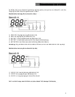
Page 21: ...le di batteria unità Volt BATTERY stima dell autonomia in percentuale della carica di batteria BATTERY MIN stima autonomia della batteria unità Minuti Nota La stima dell autonomia in minuti viene fornita anche in funzionamento da rete dell UPS Descrizione dettagliata per la Parte B a destra Parte B OUTPUT VAC tensione di uscita unità Volt OUTPUT Hz frequenza di uscita unità Hz LOAD carico applicat...

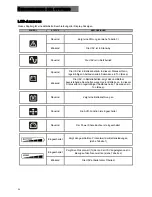
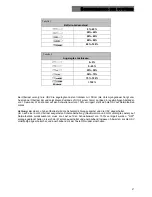
Page 22: ...ustico beep ad intervalli regolari di 4 secondi Lampeggiante L UPS in funzionamento da batteria segnala l imminente spegnimento per fine scarica In questo stato emette un segnale acustico beep ad intervalli regolari di 1 sec Fisso Indica che la batteria è guasta Fisso La funzione AVR è attiva Fisso La presa powershare è attiva Attivo Rappresenta la percentuale stimata di carica della batteria vedi...

Page 23: ... intervalli regolari di un secondo Riducendo il carico entro la soglia del 100 l UPS torna a funzionare normalmente Attenzione Se il livello di sovraccarico è troppo alto si attiva la protezione e l UPS verrà spento Per ripristinare il normale funzionamento successivamente ad un blocco causato da sovraccarico beep continuo e carico non alimentato ridurre il carico entro la soglia del 100 Tenere pr...

Page 24: ...itore Errore interno UPS Contattare il rivenditore IMPOSTAZIONE MISURE SUL DISPLAY LCD Il display LCD ha due zone sinistra Parte A e destra Parte B La zona sinistra può visualizzare i seguenti parametri Tensione d ingresso Frequenza d ingresso Tensione batteria Capacità in percentuale della batteria e Stima dell autonomia in minuti Per la zona destra i parametri disponibili sono Tensione di uscita...

Page 25: ...arte A la Tensione d ingresso e nella parte destra Parte B la Carico in percentuale Esempio di configurazione Premere SELECT per 3 secondi Premere SELECT per cambiare campo Premere ON per confermare il campo Premere SELECT per cambiare la grandezza da monitorare Premere SELECT per cambiare la grandezza da monitorare Premere ON per confermare la grandezza da monitorare ...

Page 26: ...f t 1 2 3 4 5 6 0 1 7 8 9 10 g UPS sta eseguendo il battery test Intermittente per 3 volte 0 5s on 0 5s off t 1 2 3 4 5 6 0 1 7 8 9 10 h Se non si verificano eventi riportati nei punti precedenti Non attivo t 1 2 3 4 5 6 0 1 7 8 9 10 In funzionamento da batteria è possibile tacitare il segnale acustico tenedo premuto per 3 secondi il tasto ON Questo rimarrà inibito solo se non si verificheranno gl...

Page 27: ...llarmi da parte dell UPS valori massimi 25mA 35Vdc Vce sat max 1 5V 25mA e Ingresso programmabile via RS232 5 15 Vdc PORTA USB La porta USB è usata per stabilire una comunicazione tra l UPS e il computer Quando il cavo di comunicazione è installato il software di gestione Powershield3 può scambiare informazioni con l UPS Il software può fornire informazioni dettagliate sullo stato di funzionamento...

Page 28: ...utilizzo consultare il manuale del software scaricabile dal sito web www riello ups com Per verificare la disponibilità di una versione del software più aggiornata consultare il sito del produttore SOFTWARE DI CONFIGURAZIONE Il software UPSTools permette la configurazione ed una completa visualizzazione dei parametri e dello stato dell UPS tramite porta USB Per un elenco delle possibili configuraz...

Page 29: ...S non fornisce energia ai carichi La tensione di uscita poterbbe non essere presente nella presa utilizzata Controllare il fusibile in uscita quando presente La tensione di uscita non è presente sulle prese 1 Controllare il cavo di collegamento 2 Accertare che il carico non superi la portata massima dell UPS La batteria ha ridotto la sua autonomia La batteria non è carica Ricaricare la batteria pe...

Page 30: ...tattare immediatamente il rivenditore Reciclare le batteria usate Non buttare mai le batterie nel fuoco Potrebbero esplodere Non aprire o danneggiare le batterie Il contenuto elettrolitico rilasciato è nocivo per la pelle e gli occhi Potrebbe essere tossico Per riciclare correttamente i materiali non gettare l UPS il battery box e le batterie nella spazzatura Seguire le norme e contattare il centr...

Page 31: ...il cavo delle batterie dell UPS 3 Rimuovere la piastra che blocca le batterie dopo aver svitato le viti che fissano il supporto all UPS 4 Estrarre le batterie sopra ad una superficie piana 5 Inserire le nuove batterie nell UPS 6 Avvitare il supporto delle batterie e ricollegare il cavo 7 Rimontare il pannello frontale dell UPS ...

Page 32: ...e mani 2 Svitare il supporto della batteria dall UPS e rimuovere la piastra che fissa le batterie 3 Scollegare il cavo 4 Estrarre le batterie sopra una superficie piana 5 Inserire le nuove batterie nell UPS 6 Ricollegare il cavo delle batterie e avvitare il supporto 7 Rimontare il pannello frontale dell UPS ...

Page 33: ...A RICO Da rete 110 allarme e blocco dopo 3 minuti 150 blocco dopo 5 cicli Da batteria 110 allarme e blocco dopo 30 secondi 120 blocco dopo 5 cicli TEMPO DI TRASFERI MENTO Tipico 4 msec 6 msec max BATTERIA Tensione nominale batterie 12V 24V 24V 48V 48V Tempo di ricarica Meno di 6 ore al 90 DIMENSIONI UPS Dimensioni LxHxP mm 110X240X395 160X240X435 Peso kg 7 9 9 16 16 Battery box Non disponibile AMB...

Page 34: ...allarme e blocco dopo 30 secondi 120 blocco dopo 5 cicli TEMPO DI TRASFERI MENTO Tipico 4 msec tipica 6 msec max BATTERIA Tensione nominale batterie 12V 18V 24V 48V 96V 96V Tempo di ricarica Meno di 6 ore al 90 DIMENSIONI UPS Dimensioni LxHxP mm 438X44 3X460 19 x1Ux460 438X87 9X582 19 x2Ux582 Peso kg 12 13 15 25 32 33 Battery box Tensione nominale 96 V Capacità 9 Ah Numero batterie 8 Dimensioni Lx...

Page 35: ...35 GB USER MANUAL GB ...

Page 36: ...ALLATION OF THE DVD MODELS WITH BATTERY BOX 46 POSITIONING THE FRONT PANEL LCD FOR DVD MODELS 47 INSTALLING DVR AND DVD MODELS IN A RACK CABINET 48 CONNECTION 49 CONNECTION TO THE NET TEL PROTECTION DEVICE 49 POWERSHARE 49 INSTALLING THE EMERGENCY POWER OFF EPO 50 INSTALLING AN ADDITIONAL BATTERY BOX 50 START UP SHUTDOWN 51 START UP FROM BATTERY 51 RECHARGING 51 SYSTEM DESCRIPTION 52 FRONT PANEL 5...

Page 37: ...ORT 59 COMMUNICATION SOCKET 59 SOFTWARE 60 MONITORING AND CONTROL SOFTWARE 60 CONFIGURATION SOFTWARE 60 ALARMS AND INDICATORS 61 REPLACING THE BATTERY 62 DIALOG VISION TOWER 62 DIALOG VISION RACK 63 DIALOG VISION DUAL 64 SPECIFICATIONS 65 ...

Page 38: ...ct to a CAREFUL AND THOROUGH READING OF THIS MANUAL This manual contains detailed instructions on how to use and install the UPS For information on using and getting the best performance from your UPS this manual should be kept safely near the UPS and CONSULTED BEFORE TAKING ANY ACTION Reproduction of any part of this manual partial or in full is strictly prohibited without the manufacturer s prio...

Page 39: ...ailable CHARACTERISTICS Sinusoidal output voltage Front panel LCD Microprocessor control for high reliability High frequency technology Automatic correction of input voltage fluctuations by the built in Automatic Voltage Regulator AVR The AVR compensates for input voltage variations within a defined input voltage window and maintains a stable output without resorting to batteries Using the batteri...

Page 40: ...Nominal power VA 500 800 1100 1500 2000 500 800 1100 1500 2200 3000 Nominal power W 350 540 740 1050 1350 350 540 740 1050 1540 2100 Nominal output voltage Vac 200 208 220 230 240 Dimensions LxHxD mm 110X240X395 160X240X435 438X44X460 19 x1Ux460 438X88X582 19 x2Ux582 FRONT VIEW DVT 500 800 1100 DVT 1500 2000 DVR 500 800 1100 DVD 1500 2200 3000 Dialog Vision Battery Box ...

Page 41: ...41 PRESENTATION REAR VIEW DVT 500 800 1100 DVT 1500 2000 DVR 500 800 1100 DVD 1500 ...

Page 42: ...2 Cooling fan 3 Net Tel protection 4 Input thermal protection 5 IEC network input plug 6 IEC output plug max 10A 7 Expansion slots for interface cards 8 Battery expansion connector 9 IEC output plug max 16A 10 Output thermal protection 11 USB port 12 EPO 13 Fuse 14 Powershare socket ...

Page 43: ...e contents The packaging should contain the following UPS Plastic supports DVD model only IEC 10A power cable IEC 16A for DVD models 2200 3000 only Handles kit models DVR and DVD only 2 IEC 10A connection cables IEC 16A loose plug DVD 2200 3000 models only USB cable User manual Safety manual Warranty card ...

Page 44: ...BOX PACKAGING AND CHECKING THE CONTENTS After opening the packaging check the contents The packaging should contain the following Battery Box Handles kit UPS Battery Box connection cable User manual Safety manual Warranty card Extensions ...

Page 45: ...ensation Warning A long period of use in an environment with a temperature over 25 C will shorten battery life The UPS should be placed at least 20 cm away from a monitor in order to avoid interference INSTALLING THE UPS The Dialog Vision family comprises DVT models designed for vertical installation and the DVR models which must be installed in 19 rack cabinets The DVD models can be positioned ve...

Page 46: ...ODELS WITH BATTERY BOX 1 Assemble the supports and the extension as shown in the figure 2 Put the UPS and the battery box in a vertical position and place the two supports close to them 3 Carefully insert the UPS and the battery box in the two supports ...

Page 47: ...or tower The information below explains how to rotate the display A From Rack to Tower B From Tower to Rack 1 Place the UPS flat and press the key shown 1 Place the UPS flat and press the key shown 2 Rotate the LCD display 90 2 Rotate the LCD display 90 3 Reinsert the display in its housing 3 Reinsert the display in its housing ...

Page 48: ...an be installed in a 19 rack cabinet The installation procedure is described below 1 Align and screw the handles onto the sides of the UPS 2 Secure the guides onto the rack cabinet supports with the screws 3 Insert the UPS on the mounted guides and secure it to the cabinet using the screws ...

Page 49: ...hone modem network card etc is inserted in the connector marked OUT N B This protection device limits the effects of an overvoltage but does not guarantee absolute protection POWERSHARE All the models of the Dialog Vision range are provided with an auxiliary output socket that can be configured via UPSTools The Powershare socket can be configured in five different ways refer to the UPSTools manual...

Page 50: ...MS Imax 20mA between Pin 1 and 2 of the terminal using an unshielded wire of diameter 18 22 AWG 0 75 mm2 0 3mm2 5 Reconnect the terminal to the EPO input 6 Ensure that the switch connected to the EPO contact cannot be activated by a device powered by the UPS 7 Connect the UPS to the mains power supply and switch it on using the ON key 8 Activate the EPO contact by means of the external switch to e...

Page 51: ...e current automatically increases to 6 A START UP SHUTDOWN To start up and shut down the UPS press the ON and OFF switch for at least three seconds Starting up for the first time after about 30 seconds check that the UPS is working properly 1 Simulate a mains power supply failure by unplugging the input power cable 2 The load must continue to receive power the battery mode indicator should light u...

Page 52: ...52 SYSTEM DESCRIPTION FRONT PANEL The front panel consists of a display and ON OFF and SELECT keys LCD SELECT button LCD Front panel ON button OFF button Part A Part B Part D Part C ...

Page 53: ... voltage unit Volt BATTERY estimated back up time as a percentage of the battery charge BATTERY MIN estimated battery back up time unit Minutes Note The estimated back up time in minutes is also provided when the UPS is working in mains mode Detailed description for Part B on the right Part B OUTPUT VAC output voltage unit Volt OUTPUT Hz output frequency unit Hz LOAD load applied in output as a pe...

Page 54: ...egular 4 second intervals Flashing When operating in battery mode the UPS signals that it is about to switch off due to end of discharge In this state it beeps at regular 1 second intervals Steady on Indicates that the battery is faulty Steady on The AVR function is active Steady on The Powershare socket is active Active Represents the estimated percentage of battery charge see table 1 Active Indi...

Page 55: ...nd intervals Once the load has been reduced to within the 100 threshold the UPS will return to normal operating mode Warning If the overload is too high the protection device will be activated and the UPS will shut down To restore normal operation following failure due to an overload continuous beep and load not powered reduce the load so that it falls within the 100 threshold Hold the OFF button ...

Page 56: ...eller UPS internal error Contact the reseller SETTING THE VALUES ON THE FRONT PANEL LCD The LCD has two parts left Part A and right Part B The left side displays the following parameters Input voltage Input frequency Voltage battery Capacity as a percentage of battery and Estimated back up time in minutes The parameters available on the right side are Output voltage Output frequency and Load as a ...

Page 57: ...splay Part A and Capacity as a percentage of the battery on the right side Part B Configuration example Press SELECT for 3 seconds Press SELECT to change the field Press ON to confirm the field Press SELECT to change the value to be monitored Press SELECT to change the value to be monitored Press ON to confirm the value to be monitored ...

Page 58: ...st Intermittent 1s on 1s off t 1 2 3 4 5 6 0 1 7 8 9 10 g The UPS is performing the battery test Intermittent for 3 times 0 5s on 0 5s off t 1 2 3 4 5 6 0 1 7 8 9 10 h If none of the events in the previous points has occurred Not active t 1 2 3 4 5 6 0 1 7 8 9 10 In battery mode the acoustic signal can be silenced by holding the ON key down for 3 seconds This will only remain inhibited if none of ...

Page 59: ...r signalling of alarms by the UPS maximum values 25mA 35Vdc Vce sat max 1 5V 25mA e Input programmable via RS232 5 15 Vdc USB PORT The USB port is used to establish communication between the UPS and a PC When the communication cable is installed the management software Powershield3 can exchange information with the UPS The software can provide detailed information on the UPS operating status In th...

Page 60: ...ions For more detailed information please read the user manual which can be downloaded from www riello ups com Visit the manufacturer s website to check whether a more recent version of the software is available CONFIGURATION SOFTWARE UPSTools software allows the user to configure the UPS and provides a full view of the UPS parameters and status through the USB port Refer to the UPS Configuration ...

Page 61: ...ntact the reseller The UPS is not powering the loads There may be no output voltage in the socket used Check the output fuse if present There is no output voltage on the sockets 1 Check the connection cable 2 Ensure that the load does not exceed the UPS s maximum capacity The battery has reduced its back up time The battery is not charged Recharge the battery for at least 4 hours It may not be pos...

Page 62: ...ns of leakage contact the reseller immediately Recycle the used batteries Never throw batteries into a fire as they may explode Do not open or damage the batteries The electrolyte contents are harmful to the skin and eyes and may be toxic For correct recycling do not throw the UPS the battery box or the batteries into the rubbish Contact the nearest waste recycling centre for information on how to...

Page 63: ...hands 2 Disconnect the UPS battery cable 3 Undo the screws securing the support to the UPS and remove the plate securing the batteries 4 Remove the batteries on a flat surface 5 Insert the new batteries in the UPS 6 Screw the battery support and reconnect the cable 7 Replace the front panel of the UPS ...

Page 64: ... both hands 2 Undo the screws securing the support to the UPS and remove the plate securing the batteries 3 Disconnect the cable 4 Remove the batteries on a flat surface 5 Insert the new batteries in the UPS 6 Reconnect the battery cable and secure the support 7 Replace the front panel of the UPS ...

Page 65: ... and failure after 3 minutes 150 failure after 5 cycles From battery power 110 alarm and failure after 30 seconds 120 failure after 5 cycles TRANSFER TIME Typical 4 msec 6 msec max BATTERY Nominal battery voltage 12V 24V 24V 48V 48V Recharge time Less than 6 hours at 90 DIMENSIONS UPS Dimensions LxHxD mm 110X240X395 160X240X435 Weight kg 7 9 9 16 16 Battery box Not available ENVIRONMENT Work envir...

Page 66: ...e after 30 seconds 120 failure after 5 cycles TRANSFER TIME Typical 4 msec typical 6 msec max BATTERY Nominal battery voltage 12V 18V 24V 48V 96V 96V Recharge time Less than 6 hours at 90 DIMENSIONS UPS Dimensions LxHxD mm 438X44 3X460 19 x1Ux460 438X87 9X582 19 x2Ux582 Weight kg 12 13 15 25 32 33 Battery box Nominal voltage 96 V Capacity 9 Ah Number of batteries 8 Dimensions LxHxD mm 438X87 9X582...

Page 67: ...67 D BEDIENUNGSANLEITUNG D ...

Page 68: ...ECHTE INSTALLATION DER MODELLE DVD MIT BATTERY BOX 78 AUSRICHTEN DES LCD DISPLAY FÜR MODELLE DVD 79 INSTALLATION DER MODELLE DVR UND DVD IN RACK SCHRANK 80 ANSCHLUSS 81 ANSCHLUSS AN DEN TELEFON NETZWERKSCHUTZ 81 POWER SHARE 81 INSTALLATION EMERGENCY POWER OFF EPO 82 INSTALLATION EINER ZUSÄTZLICHEN BATTERIE BOX 82 EINSCHALTEN AUSSCHALTEN 83 KALTSTART 83 AUFLADEN 83 BESCHREIBUNG DES SYSTEMS 84 BEDIE...

Page 69: ...SB ANSCHLUSS 91 KOMMUNIKATIONS STECKPLATZ 91 SOFTWARE 92 ÜBERWACHUNGS UND STEUER SOFTWARE 92 KONFIGURATIONS SOFTWARE 92 ALARME UND ANZEIGEN 93 BATTERIEWECHSEL 94 DIALOG VISION TOWER 94 DIALOG VISION RACK 95 DIALOG VISION DUAL 96 TECHNISCHE DATEN 97 ...

Page 70: ...GER LEKTÜRE DER VORLIEGENDEN BEDIENUNGSANLEITUNG kann dieses Gerät durch den Anwender installiert werden Diese Bedienungsanleitung enthält detaillierte Anweisungen zur Bedienung und Installation der USV und sollte daher in der Nähe des Gerätes sorgfältig aufbewahrt werden Vor jeglichen Arbeite an der USV Anlage sollte das Handbuch stets zu rate gezogen werden Vorbehaltlich der Genehmigung durch di...

Page 71: ...ten Überlastschutz TECHNISCHE ANGABEN Sinusförmige Ausgangsspannung LCD Display Mikroprozessorgesteuert Hochfrequenztechnologie Automatische Regulierung der Ausgangsspannung bei Schwankungen der Eingangsspannung AVR Die AVR Stabilisierungseinheit die Bestandteil aller Modelle ist gleicht Änderungen der Eingangsspannung aus und hält somit den Ausgang stabil ohne dass auf die Batterien zurückgegriff...

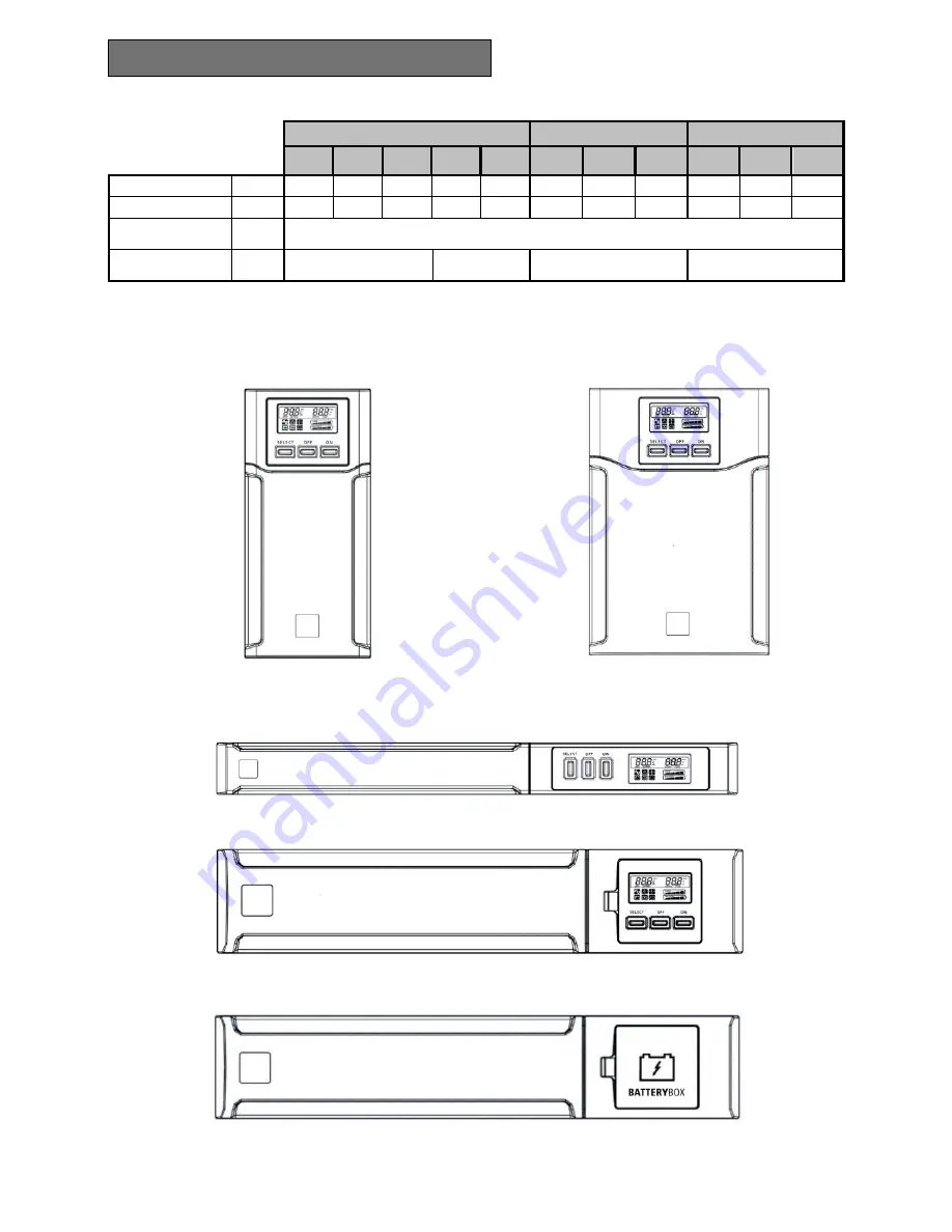
Page 72: ...Nennleistung VA 500 800 1100 1500 2000 500 800 1100 1500 2200 3000 Wirkleistung W 350 540 740 1050 1350 350 540 740 1050 1540 2100 Ausgangs Nennspannung Vac 200 208 220 230 240 Abmessungen LxHxB mm 110X240X395 160X240X435 438X44X460 19 x1Ux460 438X88X582 19 x2Ux582 VORDERSEITE DVT 500 800 1100 DVT 1500 2000 DVR 500 800 1100 DVD 1500 2200 3000 Dialog Vision Batterie Box ...

Page 73: ...73 BESCHREIBUNG RÜCKSEITE DVT 500 800 1100 DVT 1500 2000 DVR 500 800 1100 DVD 1500 ...

Page 74: ...erkschutz 4 Thermosicherung Eingang 5 Netz Eingangsstecker IEC 6 Ausgangsstecker IEC max 10A 7 Erweiterungs Steckplatz für Schnittstellen Karten 8 Anschluss Batterie Erweiterung 9 Ausgangsstecker IEC max 16A 10 Thermosicherung Ausgang 11 USB Anschluss 12 EPO Emergency Power Off 13 Sicherung 14 Powershare Stecker ...

Page 75: ...lt geprüft werden Die Verpackung muss folgendes enthalten USV Plastikhalter nur für Modell DVD Netzkabel IEC 10A IEC 16A nur für Modelle DVD 2200 3000 Griff Satz nur für Modelle DVR und DVD 2 Verbraucheranschlusskabel IEC 10A Stecker IEC 16A Nur für Modelle DVD 2200 3000 USB Kabel Bedienungsanleitung Sicherheitshandbuch Garantieschein ...

Page 76: ... KONTROLLE DES INHALTS Nach dem Öffnen der Verpackung muss als erstes der Inhalt geprüft werden Die Verpackung muss folgendes enthalten Batterie Box Griff Satz Anschlusskabel USV Batterie Box Bedienungsanleitung Sicherheitshandbuch Garantieschein Verlängerungen ...

Page 77: ...tung Ein längerer Einsatz in einem Raum mit einer Temperatur von mehr als 25 C verringert die Batterie Lebensdauer Um Störungen zu vermeiden sollte die USV in einem Abstand von mindestens 20 cm vom Monitor aufgestellt werden INSTALLATION DER USV Die Produktfamilie Dialog Vision umfasst die Modelle DVT die für eine senkrechte Aufstellung entwickelt worden sind die Modelle DVR die in 19 Schränken in...

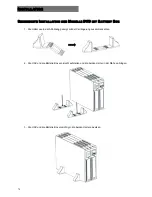
Page 78: ...T BATTERY BOX 1 Die Halter wie in der Abbildung gezeigt mit der Verlängerung zusammensetzen 2 Die USV und die Batterie Box senkrecht aufstellen und die beiden Halter in der Nähe anbringen 3 Die USV und die Batterie Box vorsichtig in die beiden Halter einsetzen ...

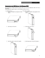
Page 79: ... Die nachstehenden Angaben erläutern wie das Display gedreht werden kann A Von Rack zu Tower B Von Tower zu Rack 1 Die USV ist aufgestellt die angegebene Taste drücken 1 Die USV ist aufgestellt die angegebene Taste drücken 2 Das Display um 90 drehen 2 Das Display um 90 drehen 3 Das Display wieder in seinen Sitz einsetzen 3 Das Display wieder in seinen Sitz einsetzen ...

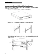
Page 80: ...den Die nachstehenden Angaben erläutern wie die Installation erfolgen muss 1 Die Griffe an der Seite der USV ausrichten und mit den Schrauben befestigen 2 Die Führungen mit den Schrauben an den Halterungen des Rack Schranks befestigen 3 Die USV in die eingebauten Führungen einsetzen und mit den entsprechenden Schrauben am Schrank befestigen ...

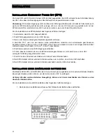
Page 81: ...ten Anschluss und die zu schützende Vorrichtung Telefon Modem Netzkarte usw in den mit OUT gekennzeichneten Anschluss eingesetzt ist Anmerkung Diese Schutzvorrichtung schränkt die Auswirkungen von Überspannung ein bietet aber keinen absoluten Schutz POWER SHARE Alle Modelle der Serie Dialog Vision sind mit einer Zusatz Ausgangsbuchse ausgestattet die über die Software UPSTools eingestellt werden k...

Page 82: ...n Vmax 60 Vdc 30 Vac RMS Imax 20mA und diesen mit einem nicht abgeschirmten Kabel mit Durchmesser 18 22 AWG 0 75 mm2 0 3mm2 anschließen 5 Die Klemme wieder an den EPO Eingang anschließen 6 Prüfen dass der Schalter der an den EPO Kontakt angeschlossen ist nicht durch eine von der USV versorgte Vorrichtung ausgelöst werden kann 7 Die USV an das Stromnetz anschließen und mit der Taste ON einschalten ...

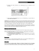
Page 83: ...ch auf 6A wenn der eingegebene Wert größer als 14Ah ist EINSCHALTEN AUSSCHALTEN Zum Ein und Ausschalten der USV jeweils den Schalter ON und OFF für mindestens drei Sekunden drücken Nur beim erstmaligen Einschalten Nach ungefähr 30 Sekunden den richtigen Betrieb der USV überprüfen 1 Einen Netzausfall durch Trennen des Netzkabels simulieren 2 Die Lasten müssen weiterhin versorgt bleiben die Anzeige ...

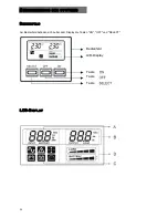
Page 84: ...84 BESCHREIBUNG DES SYSTEMS BEDIENFELD Am Bedienfeld befinden sich außer dem Display die Tasten ON OFF und SELECT LCD DISPLAY LCD Display Taste Taste Taste Bedienfeld ...

Page 85: ...mt Batteriespannung Maßeinheit Volt BATTERY Geschätzte Autonomie als Prozentwert der Batterieladung BATTERY MIN Geschätzte Autonomie der Batterie Maßeinheit Minuten Anmerkung Die geschätzte Autonomie der Batterie in Minuten wird auch bei Netzbetrieb der USV angezeigt Detaillierte Beschreibung für den Bereich B rechts Bereich B OUTPUT VAC Ausgangsspannung Maßeinheit Volt OUTPUT Hz Ausgangsfrequenz ...

Page 86: ... Ton Beep Blinkend Die USV in Batteriebetrieb zeigt das unmittelbar bevorstehende Abschalten wegen leerer Batterie an In diesem Status ertönt in regelmäßigen Abständen alle 1 Sekunden ein Ton Beep Dauernd Zeigt eine Batteriestörung an Dauernd Die AVR Funktion ist eingeschaltet Dauernd Der Power Share Buchse ist eingeschaltet Eingeschaltet Zeigt den geschätzten Prozentwert der Batterieladung an sie...

Page 87: ... Wird die Last auf den Schwellenwert von 100 verringert stellt sich die USV auf Normalbetrieb zurück Achtung Bei einer zu hohen Überlast wird die Schutzvorrichtung ausgelöst und die USV abgeschaltet Um nach einer durch Überlast ausgelösten Schutzabschaltung Dauerwarnton und nicht versorgte Lasten auf Normalbetrieb zurückzukehren muss die Last auf den Schwellenwert von 100 verringert werden OFF sol...

Page 88: ...nachrichtigen EINSTELLUNG DER MESSWERTE AM LCD DISPLAY Das LCD Display hat zwei Bereiche links Bereich A und rechts Bereich B Im linken Bereich können folgende Parameter angezeigt werden Eingangsspannung Eingangsfrequenz Batteriespannung Prozentwert Batterieleistung und Geschätzte Autonomie der Batterie in Minuten Am rechten Bereich können folgende Parameter angezeigt werden Ausgangsspannung Ausga...

Page 89: ...und am rechten Bereich Bereich B das Lastniveau in Prozent angezeigt wird Konfigurations Beispiel SELECT für 3 Sekunden drücken SELECT drücken um das Feld zu wechseln ON drücken um das Feld zu bestätigen SELECT drücken um den zu überwachenden Messwert zu ändern SELECT drücken um den zu überwachenden Messwert zu ändern ON drücken um den zu überwachenden Messwert zu bestätigen ...

Page 90: ...n 1 Sek aus t 1 2 3 4 5 6 0 1 7 8 9 10 g USV führt Batterietest aus 3 Mal abwechselnd 0 5 Sek ein 0 5 Sek aus t 1 2 3 4 5 6 0 1 7 8 9 10 h Wenn keine der oben angegebenen Ereignisse vorliegen Nicht eingeschaltet t 1 2 3 4 5 6 0 1 7 8 9 10 Im Batteriebetrieb kann das Signal durch 3 Sekunden Druck auf die Taste ON ausgeschaltet werden Das Signal bleibt nur dann ausgeschaltet wenn kein Ereignis aus d...

Page 91: ...Alarmanzeige durch die USV Max Werte 25mA 35Vdc Vce sat max 1 5V 25mA e Über RS232 programmierbarer Eingang 5 15 Vdc USB ANSCHLUSS Der USB Anschluss wird verwendet um eine Kommunikation zwischen USV und Computer herzustellen Ist das Kommunikationskabel installiert so kann die Shutdownsoftware Powershield3 Informationen mit der USV austauschen Die Software kann detaillierte Informationen zum USV Be...

Page 92: ...ationen über das erhältliche Zubehör bitten wir Sie die Website www riello ups com zu besuchen Auf der Internetseite des Herstellers kann geprüft werden ob eine aktuellere Softwareversion zur Verfügung steht KONFIGURATIONS SOFTWARE Die Software UPSTools ermöglicht die Konfiguration und komplette Anzeige des Parameter und des USV Betriebszustands über den USB Anschluss Eine Liste der dem Anwender z...

Page 93: ... könnte keine Ausgangsspannung anliegen Die Sicherung am Ausgang kontrollieren falls vorhanden An den Buchsen liegt keine Ausgangsspannung an 1 Den Anschluss des Verbindungskabels kontrollieren 2 Sicherstellen dass die Last nicht über der maximalen USV Leistung liegt Die Batterie hat eine verringerte Autonomie Die Batterie ist nicht geladen Die Batterie mindestens 4 Stunden aufladen Die Batterie k...

Page 94: ... benachrichtigen Altbatterien recyceln Batterien nie ins Feuer werfen Sie könnten explodieren Die Batterien nicht öffnen oder beschädigen Das austretende Elektrolyt ist schädlich für Haut und Augen Es könnte giftig sein Um die Materialien richtig zu recyceln die USV die Batterie Box und die Batterien nie in den Hausmüll werfen Die Vorschriften beachten und beim nächstgelegenen Recyclingzentrum Inf...

Page 95: ...riekabel trennen 3 Die Schrauben mit denen die Halterung an der USV befestigt ist abschrauben und die Batteriehalterung ausbauen 4 Die Batterie auf eine ebene Unterlage herausziehen 5 Eine neue Batterie in die USV einsetzen 6 Die Batteriehalterung festschrauben und das Batteriekabel anschließen 7 Die USV Frontblende wieder anbringen ...

Page 96: ...iehen 2 Die Batteriehalterung von der USV abschrauben und die Batteriehalterung ausbauen 3 Das Kabel trennen 4 Die Batterie auf eine ebene Unterlage herausziehen 5 Eine neue Batterie in die USV einsetzen 6 Das Batteriekabel anschließen und die Batteriehalterung festschrauben 7 Das USV Frontblende wieder anbringen ...

Page 97: ...zabschaltung nach 3 Minuten 150 Schutzabschaltung nach 5 Zyklen Im Batteriebetrieb 110 Alarm und Schutzabschaltung nach 30 Sekunden 120 Schutzabschaltung nach 5 Zyklen ÜBERBRÜCKUNGS ZEIT Typisch 4 msek 6 msek max BATTERIE Batterie Nennspannung 12V 24V 24V 48V 48V Ladedauer Weniger als 6 Stunden bis 90 ABMESSUNGEN USV Abmessungen LxHxB mm 110X240X395 160X240X435 Gewicht Kg 7 9 9 16 16 Batterie Box ...

Page 98: ... Alarm und Schutzabschaltung nach 30 Sekunden 120 Schutzabschaltung nach 5 Zyklen ÜBERBRÜCKUNGS ZEIT Typisch 4 msek typisch 6 msek max BATTERIE Batterie Nennspannung 12V 18V 24V 48V 96V 96V Ladedauer Weniger als 6 Stunden bis 90 ABMESSUNGEN USV Abmessungen LxHxB mm 438X44 3X460 19 x1Ux460 438X87 9X582 19 x2Ux582 Gewicht Kg 12 13 15 25 32 33 Battery Box Nennspannung 96 V Leistung 9 Ah Anzahl Batter...

Page 99: ...99 FR MANUEL DE L UTILISATEUR FR ...

Page 100: ...ELES DVD AVEC ARMOIRE BATTERIE 110 ORIENTATION DE L AFFICHEUR LCD POUR MODELES DVD 111 INSTALLATION DES MODELES DVR ET DVD DANS L ARMOIRE RACK 112 RACCORDEMENT 113 RACCORDEMENT A LA PROTECTION NET TEL 113 POWER SHARE 113 INSTALLATION EMERGENCY POWER OFF EPO 114 INSTALLATION ARMOIRE BATTERIE SUPPLEMENTAIRE 114 MISE EN MARCHE ARRET 115 MISE EN MARCHE SUR BATTERIE 115 RECHARGE 115 DESCRIPTION DU SYST...

Page 101: ...MMUNICATION 123 LOGICIEL 124 LOGICIEL DE SURVEILLANCE ET DE CONTROLE 124 LOGICIEL DE CONFIGURATION 124 ALARMES ET SIGNALISATIONS 125 REMPLACEMENT DE LA BATTERIE 126 DIALOG VISION TOWER 126 DIALOG VISION RACK 127 DIALOG VISION DUAL 128 DONNEES TECHNIQUES 129 ...

Page 102: ...CRUPULEUSE DU PRESENT MANUEL Ce manuel contient les instructions détaillées relatives à l utilisation et à l installation de l onduleur Pour avoir des informations concernant l utilisation et obtenir les meilleures performances de votre appareil le présent manuel devra être conservé avec soin à proximité de l onduleur et CONSULTE AVANT TOUTE OPERATION Toute reproduction intégrale ou partielle du p...

Page 103: ...he ou l arrêt la protection contre la surcharge CARACTERISTIQUES Tension de sortie sinusoïdale Afficheur LCD Microprocesseur de contrôle garantissant une haute fiabilité Technologie à haute fréquence Correction automatique des fluctuations de la tension d entrée AVR Le dispositif de stabilisation AVR présent sur tous les modèles compense les variations de tension en entrée et maintient la sortie s...

Page 104: ...nominale VA 500 800 1100 1500 2000 500 800 1100 1500 2200 3000 Puissance nominale W 350 540 740 1050 1350 350 540 740 1050 1540 2100 Tension nominale de sortie Vac 200 208 220 230 240 Dimensions LxHxP mm 110X240X395 160X240X435 438X44X460 19 x1Ux460 438X88X582 19 x2Ux582 VUE DE FACE DVT 500 800 1100 DVT 1500 2000 DVR 500 800 1100 DVD 1500 2200 3000 Dialog Vision Armoire batterie ...

Page 105: ...105 PRESENTATION VUE ARRIERE DVT 500 800 1100 DVT 1500 2000 DVR 500 800 1100 DVD 1500 ...

Page 106: ...dissement 3 Protection Net Tel 4 Protection thermique d entrée 5 Fiche d entrée réseau IEC 6 Prise de sortie IEC 10A maxi 7 Slot d extension pour cartes interface 8 Connecteur d extension batterie 9 Prise de sortie IEC 16A maxi 10 Protection thermique de sortie 11 Port USB 12 EPO 13 Fusible 14 Prise Powershare ...

Page 107: ...ballage doit contenir Onduleur Supports en plastique Pour modèle DVD seulement Câble d alimentation IEC 10A IEC 16A pour modèles DVD 2200 3000 seulement Kit poignées Pour modèles DVR et DVD seulement 2 câbles de raccordement IEC 10A Fiche volante IEC 16A Pour modèles DVD 2200 3000 seulement Câble USB Manuel utilisateur Manuel de sécurité Feuille de garantie ...

Page 108: ...T VERIFICATION DE SON CONTENU Après avoir ouvert l emballage commencer par vérifier son contenu L emballage doit contenir Armoire batterie Kit poignées Câble de raccordement Onduleur Armoire batterie Manuel utilisateur Manuel de sécurité Feuille de garantie Rallonges ...

Page 109: ...un environnement caractérisé par une température supérieure à 25 C réduit la durée de vie des batteries De plus il est recommandé de positionner l onduleur à une distance minimum de 20 cm de l écran pour éviter toute interférence INSTALLATION DE L ONDULEUR La famille Dialog Vision comprend les modèles DVT conçus pour être positionnés verticalement les modèles DVR qui doivent être installés dans de...

Page 110: ...TERIE 1 Assembler les supports avec la rallonge selon les indications de la figure 2 Mettre l onduleur et l armoire batterie en position verticale et placer les deux supports à proximité de ceux ci 3 Enfiler avec soin l onduleur et l armoire batterie dans les deux supports ...

Page 111: ...liquent la façon d orienter l afficheur A De Rack à Tour B De Tour à Rack 1 Une fois que l onduleur est placé sur une surface plane appuyer sur la touche indiquée 1 Une fois que l onduleur est placé sur une surface plane appuyer sur la touche indiquée 2 Tourner l afficheur LCD de 90 2 Tourner l afficheur LCD de 90 3 Replacer l afficheur dans son logement 3 Replacer l afficheur dans son logement ...

Page 112: ...e rack de 19 Les indications suivantes décrivent les différentes phases d installation 1 Aligner et fixer poignées à l aide des vis les sur les côtés de l onduleur 2 Fixer les rails aux supports de l armoire rack à l aide des vis 3 Insérer l onduleur dans les rails montés et le bloquer à l armoire à l aide des vis prévues à cet effet ...

Page 113: ... que le dispositif à protéger téléphone modem carte de réseau etc est bien raccordé au connecteur reportant l indication OUT N B Ce dispositif de protection limite les effets de la surtension mais ne garantit pas une protection absolue POWER SHARE Tous les modèles de la série Dialog Vision sont munis d une prise de sortie auxiliaire configurable par UPSTools La prise Power Share peut être configur...

Page 114: ...e d un fil non blindé de 18 22 AWG 0 75 mm2 0 3mm2 de diamètre 5 Rebrancher la borne à l entrée EPO 6 Vérifier que l interrupteur raccordé au contact EPO ne puisse pas être activé par un dispositif alimenté par l onduleur 7 Raccorder l onduleur au réseau et le mettre en marche en appuyant sur la touche ON 8 Activer le contact EPO à l aide de l interrupteur extérieur pour vérifier l arrêt de l ondu...

Page 115: ...matiquement à 6A MISE EN MARCHE ARRET Pour mettre en marche et arrêter l onduleur appuyer respectivement sur l interrupteur ON et OFF pendant au moins trois secondes Première mise en marche seulement au bout de 30 s environ vérifier le bon fonctionnement de l onduleur 1 Simuler un coupure électrique en débranchant le câble d alimentation du réseau 2 La charge doit continuer à être alimentée le voy...

Page 116: ...PTION DU SYSTEME PANNEAU FRONTAL Sur le panneau frontal se trouvent les touches ON OFF et SELECT AFFICHEUR LCD Afficheur LCD Panneau frontal Partie A Partie B Partie D Partie C Bouton ON Bouton OFF Bouton SELECT ...

Page 117: ...ATTERY estimation de l autonomie en pourcentage de la charge de la batterie BATTERY MIN estimation de l autonomie de la batterie unité Minute Note L estimation de l autonomie en minutes est également fournie en cas de fonctionnement sur réseau de l onduleur Description détaillée de la Partie B à droite Partie B OUTPUT VAC tension de sortie unité Volt OUTPUT Hz fréquence de sortie unité Hz LOAD cha...

Page 118: ...condition il émet un signal sonore bip toutes les 4 secondes Clignotante Lorsqu il fonctionne sur batterie l onduleur signale l arrêt imminent pour fin de décharge Quand il se trouve dans cette condition il émet un signal sonore bip toutes les secondes Fixe Indique que la batterie est en panne Fixe La fonction AVR est active Fixe La prise power share est active Active Représente le pourcentage est...

Page 119: ...es les secondes Dès que la charge redescend sous le plafond de 100 l onduleur recommence à fonctionner normalement Attention Si le niveau de surcharge est trop élevé la protection s active et l onduleur s éteint Pour rétablir le fonctionnement normal suite à un arrêt total dû à une surcharge bip continu et charge non alimentée réduire la charge sous le plafond de 100 Appuyer de manière continue su...

Page 120: ...ur Erreur interne onduleur Contacter le revendeur INSTAURATION DES MESURES SUR L AFFICHEUR LCD L afficheur LCD a deux zones une à gauche Partie A et une à droite Partie B Dans la zone de gauche sont affichés les paramètres suivants Tension d entrée Fréquence d entrée Tension batterie Capacité en pourcentage de la batterie et Estimation de l autonomie en minutes Pour la zone de droite les paramètre...

Page 121: ... A la Tension d entrée et dans la partie droite Partie B la Charge en pourcentage Exemple de configuration Appuyer sur SELECT pendant 3 secondes Appuyer sur SELECT pour changer de champ Appuyer sur ON pour valider le champ Appuyer sur SELECT pour changer la mesure à afficher Appuyer sur SELECT pour changer la mesure à afficher Appuyer sur ON pour valider la mesure à afficher ...

Page 122: ...s off t 1 2 3 4 5 6 0 1 7 8 9 10 g Test batterie en cours par l onduleur Intermittent 3 fois 0 5s on 0 5s off t 1 2 3 4 5 6 0 1 7 8 9 10 h Si aucune des situations reportées ci dessus ne se produit Non actif t 1 2 3 4 5 6 0 1 7 8 9 10 En fonctionnement sur batterie il est possible d exclure le signal sonore en pressant la touche ON pendant 3 secondes Le signal sonore ne sera inhibé qu en l absence...

Page 123: ...uleur valeurs maximums 25mA 35Vcc Vce sat maxi 1 5V 25mA e Entrée programmable par RS232 5 15 Vdc PORT USB Le port USB est utilisé pour établir une communication entre l onduleur et l ordinateur Une fois que le câble de communication est installé le logiciel de gestion Powershield3 peut échanger des informations avec l onduleur Le logiciel peut fournir des informations détaillées sur l état de fon...

Page 124: ...es sont disponibles et pour plus d informations concernant les accessoires disponibles consulter le site web www riello ups com Pour vérifier la disponibilité d une version du logiciel plus actuelle consulter le site du fabricant LOGICIEL DE CONFIGURATION Le logiciel UPSTools permet d effectuer la configuration et d obtenir un affichage complet des paramètres et de l état de l onduleur par port US...

Page 125: ...rges La tension de sortie pourrait ne pas être présente dans la prise utilisée Contrôler le fusible en sortie si présent La tension de sortie n est pas présente sur les prises 1 Contrôler le câble de raccordement 2 Vérifier que la charge ne dépasse pas le débit maximum de l onduleur La batterie a réduit son autonomie La batterie n est pas chargée Recharger la batterie pendant 4 heures au minimum L...

Page 126: ...r immédiatement le revendeur Recyclage des batteries usées Ne jamais jeter les batteries dans le feu car elles pourraient exploser Ne jamais tenter d ouvrir ou d endommager les batteries L électrolyte qu elles contiennent est nocif pour la peau et les yeux Il pourrait s avérer toxique En vue de recycler correctement les matériaux ne pas jeter l onduleur l armoire batterie ou les batteries dans les...

Page 127: ... le câble des batteries 3 Enlever la plaque qui bloque les batteries après avoir dévissé les vis qui fixent le support de l onduleur 4 Dégager les batteries et les placer sur une surface plane 5 Introduire les nouvelles batteries dans l onduleur 6 Visser le support des batteries et rebrancher le câble 7 Remonter le panneau frontal de l onduleur ...

Page 128: ...isser le support de la batterie de l onduleur et enlever la plaque qui fixe les batteries 3 Débrancher le câble 4 Dégager les batteries et les placer sur une surface plane 5 Introduire les nouvelles batteries dans l onduleur 6 Rebrancher le câble des batteries et visser le support 7 Remonter le panneau frontal de l onduleur ...

Page 129: ...rme et arrêt total au bout de 3 minutes 150 arrêt total au bout de 5 cycles Sur batterie 110 alarme et arrêt total au bout de 30 secondes 120 arrêt total au bout de 5 cycles TEMPS DE TRANSFERT Typique 4 ms 6 ms maxi BATTERIE Tension nominale batterie 12V 24V 24V 48V 48V Temps de recharge Moins de 6 heures à 90 DIMENSIONS Onduleur Dimensions LxHxP mm 110X240X395 160X240X435 Poids kg 7 9 9 16 16 Arm...

Page 130: ...alarme et arrêt total au bout de 30 secondes 120 arrêt total au bout de 5 cycles TEMPS DE TRANSFERT Typique 4 ms typique 6 ms maxi BATTERIE Tension nominale batterie 12V 18V 24V 48V 96V 96V Tempo de recharge Moins de 6 heures à 90 DIMENSIONS Onduleur Dimensions LxHxP mm 438X44 3X460 19 x1Ux460 438X87 9X582 19 x2Ux582 Poids kg 12 13 15 25 32 33 Armoire batterie Tension nominale 96 V Capacité 9 Ah N...

Page 131: ...131 E MANUAL DE USO E ...

Page 132: ...ELOS DVD CON PACK DE BATERÍAS 142 ORIENTACIÓN DE LA PANTALLA LCD PARA MODELOS DVD 143 INSTALACIÓN DE LOS MODELOS DVR Y DVD EN UN ARMARIO RACK 144 CONEXIÓN 145 CONEXIÓN A LA PROTECCIÓN NET TEL 145 POWER SHARE 145 INSTALACIÓN DEL EMERGENCY POWER OFF EPO 146 INSTALACIÓN DEL PACK DE BATERÍAS ADICIONAL 146 ENCENDIDO APAGADO 147 ENCENDIDO CON LA BATERÍA 147 RECARGA 147 DESCRIPCIÓN DEL SISTEMA 148 PANEL ...

Page 133: ...A DE COMUNICACIÓN 155 SOFTWARE 156 SOFTWARE DE SUPERVISIÓN Y CONTROL 156 SOFTWARE DE CONFIGURACIÓN 156 ALARMAS Y SEÑALES 157 SUSTITUCIÓN DE LA BATERÍA 158 DIALOG VISION TOWER 158 DIALOG VISION RACK 159 DIALOG VISION DUAL 160 CARACTERÍSTICAS TÉCNICAS 161 ...

Page 134: ... ATENTA Y MINUCIOSA DE ESTE MANUAL Este manual contiene instrucciones detalladas para el uso y la instalación del SAI Para más información acerca del uso y para conseguir el máximo de las prestaciones de su aparato este manual deberá guardarse cuidadosamente cerca del SAI y CONSULTARLO ANTES DE MANIPULARLO Queda terminantemente prohibida la reproducción de cualquier parte de este manual así como d...

Page 135: ...tección de sobrecarga CARACTERÍSTICAS Tensión de salida sinusoidal Pantalla LCD Microprocesador de control que garantice una fiabilidad elevada Tecnología de alta frecuencia Corrección automática de las fluctuaciones de la tensión de entrada AVR El dispositivo de estabilización AVR que se encuentra en todos los modelos compensa las variaciones de la tensión de entrada y mantiene estable la salida ...

Page 136: ...ominal VA 500 800 1100 1500 2000 500 800 1100 1500 2200 3000 Potencia nominal W 350 540 740 1050 1350 350 540 740 1050 1540 2100 Tensión nominal de salida Vac 200 208 220 230 240 Dimensiones LxAxP mm 110X240X395 160X240X435 438X44X460 19 x1Ux460 438X88X582 19 x2Ux582 VISTA DELANTERA DVT 500 800 1100 DVT 1500 2000 DVR 500 800 1100 DVD 1500 2200 3000 Pack de baterías Dialog Vision ...

Page 137: ...137 PRESENTACIÓN VISTA POSTERIOR DVT 500 800 1100 DVT 1500 2000 DVR 500 800 1100 DVD 1500 ...

Page 138: ...n 3 Protección Net Tel 4 Protección térmica de entrada 5 Clavija de entrada de red IEC 6 Toma de salida IEC máx 10A 7 Ranura de expansión para tarjetas de interfaz 8 Conector de expansión de la batería 9 Toma de salida IEC máx 16A 10 Protección térmica de salida 11 Puerto USB 12 EPO 13 Fusible 14 Toma Powershare ...

Page 139: ...da El embalaje debe contener SAI Soportes de plástico solo para el modelo DVD Cable de alimentación IEC 10A IEC 16A solo para modelos DVD 2200 3000 Conjunto de tiradores solo para los modelos DVR y DVD 2 cables de conexión IEC 10A Clavija IEC 16A solo para los modelos DVD 2200 3000 Cable USB Manual de uso Manual de seguridad hoja de garantía ...

Page 140: ...Y COMPROBACIÓN DEL CONTENIDO Tras la apertura del embalaje compruebe el contenido antes que nada El embalaje debe contener Pack de baterías Conjunto de tiradores Cable de conexión USB Pack de baterías Manual de uso Manual de seguridad hoja de garantía Alargadores ...

Page 141: ...ngado en un entorno con una temperatura superior a los 25ºC reduce la duración de la batería Además sitúelo a una distancia igual o superior a 20 cm de distancia del monitor para evitar así que se produzcan interferencias INSTALACIÓN DEL SAI La familia Dialog Vision comprende los modelos DVT diseñados para que se coloquen en vertical los modelos DVR que se deben instalar en armarios rack de 19 pul...

Page 142: ...ACK DE BATERÍAS 1 Ensamble los soportes junto al alargador como se indica en la figura 2 Ponga el SAI y el pack de baterías en posición vertical y coloque los dos soportes cerca de los equipos 3 Introduzca el SAI y el pack de baterías en los soportes con cuidado ...

Page 143: ...as siguientes indicaciones explican cómo se puede girar la pantalla A De rack a torre B De torre a rack 1 Al estar el SAI en el suelo pulse el botón que se indica 1 Al estar el SAI en el suelo pulse el botón que se indica 2 Gire la pantalla LCD 90º 2 Gire la pantalla LCD 90º 3 Vuelva a introducir la pantalla en su sitio 3 Vuelva a introducir la pantalla en su sitio ...

Page 144: ...de 19 Las indicaciones que vienen a continuación describen cómo se debe realizar la instalación 1 Alinee y fije con los tornillos los tiradores en los lados del SAI 2 Fije las guías a los soportes del armario rack con los tornillos 3 Introduzca el SAI en las guías montadas y fíjelo al armario mediante los correspondientes tornillos ...

Page 145: ...módem tarjeta de red etc esté introducido en el conector OUT NOTA Este dispositivo de protección limita los efectos del fenómeno de la sobretensión pero no garantiza una protección absoluta POWER SHARE Todos los modelos de la serie Dialog Vision vienen dotados con una toma de salida auxiliar configurable a través de UPSTools La toma Power Share se puede configurar de los cinco modos distintos véas...

Page 146: ...S Imax 20mA conectándolo con un hilo sin blindaje de diámetro 18 22 AWG 0 75 mm2 0 3mm2 5 Vuelva a conectar el borne a la entrada EPO 6 Compruebe que el interruptor conectado al contacto EPO no se pueda activar desde un dispositivo al que alimente el SAI 7 Conecte el SAI a la red y enciéndalo con la tecla ON 8 Active el contacto EPO mediante el interruptor externo para comprobar que se ha apagado ...

Page 147: ...asa automáticamente a 6A ENCENDIDO APAGADO Para encender y apagar el SAI pulse respectivamente el interruptor ON y OFF durante tres segundos como mínimo Sólo para el primer encendido transcurridos alrededor de 30 s compruebe el correcto funcionamiento del SAI 1 Simule un apagón desenchufando el cable de alimentación de red 2 La carga debe seguir siendo alimentada el indicador de funcionamiento con...

Page 148: ...148 DESCRIPCIÓN DEL SISTEMA PANEL FRONTAL En el panel frontal además de la pantalla están presentes los botones ON OFF y SELECT PANTALLA LCD Display LCD Panel frontal Botòn ON Botòn SELECT Botòn OFF ...

Page 149: ...os BATTERY estimación de la autonomía en tantos por ciento de la carga de la batería BATTERY MIN estimación de la autonomía de la batería unidad Minutos Nota La estimación de la autonomía en minutos se suministra también cuando el SAI funciona con la red Descripción detallada para la parte B a la derecha Parte B OUTPUT VAC tensión de salida unidad Voltios OUTPUT Hz frecuencia de salida unidad Hz L...

Page 150: ...tado emite una señal acústica bip a intervalos regulares de 4 segundos Parpadeando El SAI cuando funciona con la batería indica el apagado inminente debido a la descarga de ésta En este estado emite una señal acústica bip a intervalos regulares de 1 s Fijo Indica que la batería se ha averiado Fijo La función AVR está activa Fijo La toma powershare está activa Activo Representa el tanto por ciento ...

Page 151: ...la alarma bip a intervalos regulares de un segundo Si se reduce la carga hasta el umbral del 100 el SAI vuelva a funcionar normalmente Atención Si el nivel de sobrecarga es demasiado alto se activa la protección y el SAI se apagará Para volver al funcionamiento normal tras un bloqueo provocado por la sobrecarga bip continuo y carga no alimentada reduzca la carga hasta el umbral del 100 Mantenga pr...

Page 152: ...ndedor CONFIGURACIÓN DE LAS MEDIDAS EN LA PANTALLA LCD La pantalla LCD tiene dos zonas izquierda Parte A y derecha Parte B En la zona izquierda puede visualizar los siguientes parámetros Tensión de entrada Frecuencia de entrada Tensión de la batería Capacidad en tantos por ciento de la batería y Estimación de la autonomía expresada en minutos En la zona derecha los parámetros disponibles son Tensi...

Page 153: ...te A la Tensión de entrada y en la parte derecha Parte B la Capacidad en tantos por ciento de la batería Ejemplo de configuración Pulsar SELECT durante 3 seg Pulsar SELECT para cambiar de campo Pulsar ON para confirmar el campo Pulsar SELECT para cambiar el valor a supervisar Pulsar SELECT para cambiar el valor a supervisar Pulsar ON para confirmar el valor a supervisar ...

Page 154: ... 4 5 6 0 1 7 8 9 10 g El SAI está realizando la prueba de baterías Intermitente 3 veces 0 5 s encendido 0 5 s no t 1 2 3 4 5 6 0 1 7 8 9 10 h Si no se verifican eventos de los que se haya informado en los puntos precedentes Inactivo t 1 2 3 4 5 6 0 1 7 8 9 10 Cuando funciona con la batería es posible silenciar la señal acústica presionado durante 3 segundos el botón ON Permanecerá apagado solament...

Page 155: ...ñal de alarmas por parte del SAI valores máximos 25mA 35Vdc Vce sat máx 1 5V 25mA e Entrada programable a través del RS232 5 15 Vdc PUERTO USB El puerto USB se emplea para establecer una comunicación entre el SAI y el ordenador Cuando se instala el cable de comunicación el software de gestión Powershield3 puede intercambiar información con el SAI El software puede suministrar información detallada...

Page 156: ...nes del programa de instalación Para verificar la disponibilidad de otros accesorios consultar la página web www riello ups com Para comprobar si existe una versión del software más actualizada consulte la página del fabricante SOFTWARE DE CONFIGURACIÓN El software UPSTools permite la configuración y una completa visualización de los parámetros y del estado del SAI a través del puerto USB Si neces...

Page 157: ...inistra energía a las cargas Podría ser que no haya tensión de salida en la toma empleada Compruebe el fusible de salida si existe No hay tensión de salida en las tomas 1 Compruebe el cable de conexión 2 Compruebe que la carga no supere la capacidad máxima del SAI La batería ha reducido su autonomía La batería no está cargada Recargue la batería por un período no inferior a 4 horas La batería podr...

Page 158: ...nta señales de pérdida contacte inmediatamente con el vendedor Recicle las baterías usadas Nunca arroje las baterías al fuego Podrían explotar No abra o dañe las baterías El contenido electrolítico que se vierte es nocivo para la piel y los ojos Podría ser tóxico Para reciclar correctamente los materiales no tire el SAI el pack de baterías y las baterías a la basura Siga las normas y contacte con ...

Page 159: ...as del SAI 3 Retire la placa que bloquea las baterías una vez que haya desatornillado los tornillos que anclan el soporte al SAI 4 Extraiga las baterías y colóquelas en una superficie plana 5 Introduzca las nuevas baterías en el SAI 6 Atornille el soporte de las baterías y vuelva a conectar el cable 7 Vuelva a colocar el panel frontal del SAI ...

Page 160: ...rnille el soporte de la batería del SAI y retire la placa que fija las baterías 3 Desconecte el cable 4 Extraiga las baterías y colóquelas en una superficie plana 5 Introduzca las baterías nuevas en el SAI 6 Vuelva a conectar el cable de las baterías y atornille el soporte 7 Vuelva a colocar el panel frontal del SAI ...

Page 161: ...CAR GA Con la red 110 alarma y bloqueo tras 3 minutos 150 bloqueo tras 5 ciclos Con la batería 110 alarma y bloqueo tras 30 segundos 120 bloqueo tras 5 ciclos TIEMPO DE TRANSFE RENCIA Lo habitual 4 ms 6 ms máx BATERÍA Tensión nominal de las baterías 12V 24V 24V 48V 48V Tiempo de recarga Menos de 6 horas al 90 DIMENSIONE S SAI Dimensiones LxAxP mm 110X240X395 160X240X435 Peso kg 7 9 9 16 16 Pack de...

Page 162: ...10 alarma de bloqueo tras 30 segundos 120 bloqueo tras 5 ciclos TIEMPO DE TRANSFE RENCIA Lo habitual 4 ms típica 6 ms máx BATERÍA Tensión nominal de las baterías 12V 18V 24V 48V 96V 96V Tiempo de recarga Menos de 6 horas al 90 DIMENSIO NES SAI Dimensiones LxAxP mm 438X44 3X460 19 x1Ux460 438X87 9X582 19 x2Ux582 Peso kg 12 13 15 25 32 33 Pack de baterías Tensión nominal 96 V Capacidad 9 Ah Número d...

Page 163: ......

Page 164: ......

Reviews: