1
20013744
GB
TECHNICAL DATA
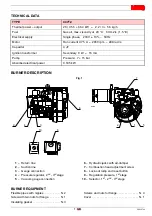
BURNER DESCRIPTION
BURNER EQUIPMENT
Flexible pipes with nipples. . . . . . . . . . . N. 2
Screws and nuts for flange. . . . . . . . . . . . . . N. 4
Screw with two nuts for flange. . . . . . . . N. 1
Cover . . . . . . . . . . . . . . . . . . . . . . . . . . . . . . N. 1
Insulating gasket . . . . . . . . . . . . . . . . . . N. 3
TYPE
447T2
Thermal power – output
26 / 35.5 ÷ 66.4 kW
–
2.2 / 3 ÷ 5.6 kg/h
Fuel
Gas oil, max. viscosity at 20 °C: 6 mm2/s (1.5° E)
Electrical supply
Single phase, 230 V ± 10% ~ 50Hz
Motor
Run current 0.75 A
–
2850 rpm – 298 rad/s
Capacitor
4
F
Ignition transformer
Secondary 8 kV
–
16 mA
Pump
Pressure: 7 ÷ 15 bar
Absorbed electrical power
0.185 kW
D8390
3
4
6
8
1
2
7
5
1
2
3
9
10
Fig. 1
1
– Return line
2
– Suction line
3
– Gauge connection
4
– Pressure regulator, 2
nd
- 3
rd
stage
5
– Vacuum gauge connection
6
– Hydraulic jacks with air-damper
7
– Combustion head adjustment screw
8
– Lock-out lamp and reset button
9
– Regulation pressure, 1
st
stage
10
– Selector, 1
st
- 2
nd
- 3
rd
stage


