7
2915246
GB
FIXING OF THE ELECTRICAL WIRES
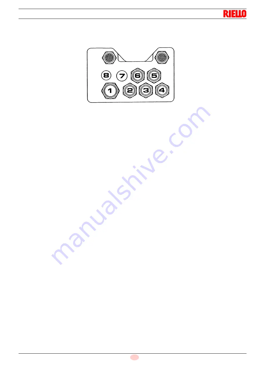
All the electrical wires, which are to be connected to the terminal block 7) (fig. 1) shall pass through the fair leads 6) (fig.
1) as per this scheme.
1 - Three phase supply:
fair lead Pg 21
2 - Single phase supply:
fair lead Pg 13.5
3 - Adjustment thermostat:
fair lead Pg 13.5
4 - Safety thermostat:
fair lead Pg 13.5
5 - Gas train:
fair lead Pg 13.5, sheath ø 13
6 - 2nd stage thermostat:
fair lead Pg 13.5
(probe for modulating version)
7 - Pre-sheared hole:
fair lead Pg 13.5 (for power controller - modulating version)
8 - Pre-sheared holeg
Further prospective signals or controls can be connected to the burner wiring terminal board by removing the metal weld-
nuts from the pre-sheared holes and inserting a commun fair lead for the passage and the clamping of the leads.
NOTES
- Do not exchange the neutral wire with the phase (avoid the plug-pin connection).
- Carry out a safe earth connection.
- Check the stop of the burner, by opening the boiler thermostat and the burner lock-out, by disconnecting the lead from
the flame probe.
WARNING
When closing the burner on its slide-bars, pull towards the outside the high voltage cable and the cable of the flame de-
tection probe, till to little tension.
D2184


