3399
8
GB
4.4
MAINTENANCE POSITION
THE ACCESSIBILITY TO THE NOZZLE, THE DIFFUSER DISC AND THE ELECTRODES IS MADE
EASY IN 2 WAYS:
³
Remove the burner out of the boiler, after loosing
the fixing nut to the flange.
³
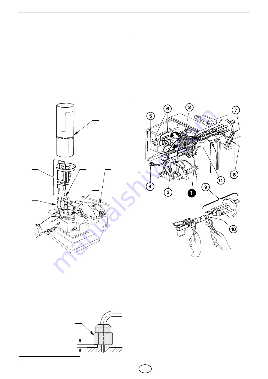
Hook the burner to the flange (1), by removing the
flame tube (2) after loosing the fixing screws (3).
³
Remove the small cables (4) from the electrodes
and the diffuser disc-holder assembly (5) from
the nozzle-holder assembly after loosing its fixing
screw (3, fig. 11-12, page 7).
³
Screw the nozzle (6) correctly and tighten it as
shown in the figure.
³
Remove nozzle-holder assembly (1) after loosing
screws (2) and nut (3), remove the small cables
(6) from the control box, the socket (4) and the
flame detector (5).
³
Withdraw the small cables (6) from the electro-
des, remove the diffuser disc-holder assembly (9)
from the nozzle-holder assembly (1) after loosing
screw (3, fig. 11-12, page 7).
³
Screw the nozzle (10) correctly and tighten it as
shown in figure.
Fig. 13
TIGHTEN WITHOUT MOVING
BACKWARDS TO THE END
D5684
9
Fig. 15
D8220
Fig. 14
5
ATTENTION
³
During the reassembly of the nozzle-holder assembly screw the nut (3) as shown in fig. 15.
³
In order to guarantee the sealing of the fan in its seat, make sure that there is at least 1 mm of spring tension
between nozzle-holder assembly and casing. Therefore the fixing split pin (11) will have to be extended at
least of 1 mm beyond the flange of the nozzle-holder assembly.
D8217
4
6
3
1
2


