‐
17
‐
C
ONNECTIVITY
P
ANEL
(CP)
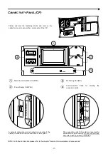
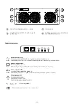
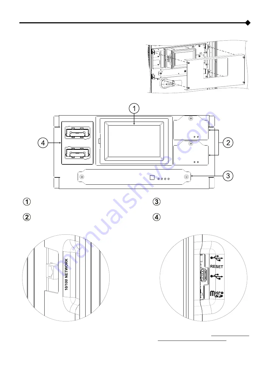
Please unscrew the fastening knobs and remove the
protection cover to access the components of the CP.
Main Communication Unit (MCU)
Monitoring Unit (MU)
Power Supply Unit (PSU)
Communication Slots for housing the
expansion cards.
A network connection port is located on one side of the
display to enable the remote operation of the system.
The connection ports (SA ports) are reserved for
trained service personel only. Do not connect to the
SA ports unless specifically instructed.
NOTE: For further information please refer to the chapter “Remote Communication and accessories”
Summary of Contents for multipower BTC 170
Page 1: ......
Page 2: ......
Page 6: ...6...
Page 8: ...8 GENERAL VIEWS Front view Back view Frame Handle with lock Door Back Panel...
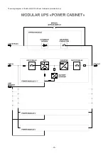
Page 20: ...20 The wiring diagram of the Modular UPS Power Cabinet is provided below...
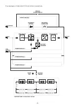
Page 23: ...23 The wiring diagram of the Modular UPS Combo Cabinet is provided below...
Page 54: ...54 Combo Cabinet...
Page 55: ...55 Battery Cabinet...
Page 82: ......
Page 83: ......
Page 84: ...0MNMPWK25R1ENUA...


