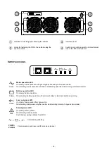
‐
21
‐
M
ODULAR
B
ATTERY
C
ABINET
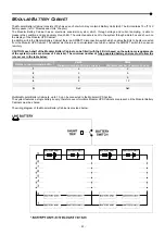
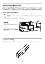
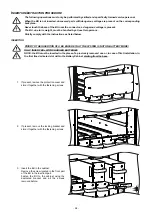
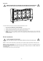
The Modular Battery Cabinet consists of 9 shelves, each of which may contain 4 Battery Units (BU). The BU contains 10 off 12V
battery packs (ref to “Modules and Units” chapter).
The Modular Battery Cabinet has an electronic supervision system which, through voltage and current sampling, is able to
measure the condition and any anomaly of each BU. The collected data is sent to the system through a data bus and shown on
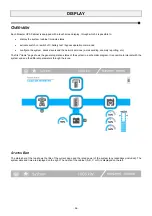
the display of the Modular UPS Cabinet.
In addition, within the Modular Battery Cabinet there is a SWBATT disconnection switch which enables the BUs to be disconnected
from the Modular UPS Cabinet. The cabinet also features an opto-isolated input which enables the SWBATT switch to be opened
remotely.
CAUTION: each shelf of the Modular Battery Cabinet can be filled (with the 4 BUs) based on the autonomy requirements
of the system (up to a maximum of 9 shelves). The minimum number of fully populated battery shelves must follow the
rule set out in the table below:
Number of non-redundant PMs
PM25
Minimum number of battery shelves
PM42
Minimum number of battery shelves
1
2
2
2
3 5
3
5
9
4
8 12
..
…
…
N
Nx2 Nx3
Multiple Modular Battery Cabinets, up to 10, can be connected to the Modular UPS System.
The system features a single battery supply, therefore even if multiple Modular UPS Cabinets are present, all the Modular Battery
Cabinets must be shared.
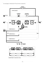
The wiring diagram of the Modular Battery Cabinet is provided below.
Summary of Contents for multipower BTC 170
Page 1: ......
Page 2: ......
Page 6: ...6...
Page 8: ...8 GENERAL VIEWS Front view Back view Frame Handle with lock Door Back Panel...
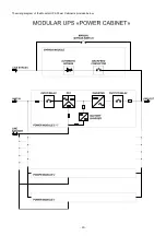
Page 20: ...20 The wiring diagram of the Modular UPS Power Cabinet is provided below...
Page 23: ...23 The wiring diagram of the Modular UPS Combo Cabinet is provided below...
Page 54: ...54 Combo Cabinet...
Page 55: ...55 Battery Cabinet...
Page 82: ......
Page 83: ......
Page 84: ...0MNMPWK25R1ENUA...


