‐
31
‐
M
ONITORING
U
NIT
(MU)
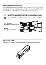
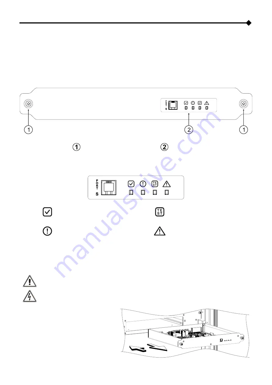
Within the Modular UPS Power Cabinet, the Monitoring Unit (MU) monitors the status of the internal and external disconnection
switches, the status of the Power Supply Unit and the internal and external temperature values.
Within the Battery Cabinet, the MU monitors the Power Supply Unit, the internal temperature values and supervises the status of
each Battery Unit.
During the first installation of a single Cabinet, via a specific set up made within the MU, the address and the type of cabinet must
be configured (ref. to “Configuration” chapter)
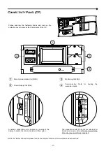
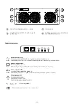
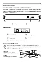
Fastening knobs
Interface panel
I
NTERFACE PANEL
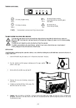
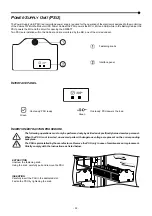
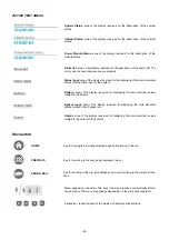
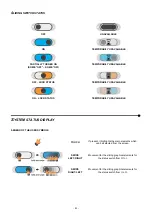
Green
On steady:
MU ready
Green
Slow blinking
: Testing
Yellow
On steady
: Anomaly
Red
On steady
: Alarm
PORT S
Communication ports reserved for service personnel
I
NSERTION
/
EXTRACTION PROCEDURE
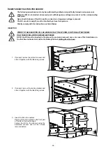
The following operations must only be performed by skilled and specifically trained service personel.
When the MU is not inserted, uncovered parts with dangerous voltage are present on the corresponding
backplane.
The MU is preinstalled by the manufacturer. Remove the MU only in case of maintenance or replacement.
Strictly comply with the instructions as listed below.
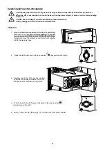
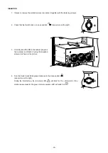
EXTRACTION
Unscrew the two side fastening knobs.
Using the knobs, carefully pull and remove the MU.
INSERTION
Carefully insert the MU into the dedicated slot.
Fasten the MU by tightening the side knobs.
Summary of Contents for multipower BTC 170
Page 1: ......
Page 2: ......
Page 6: ...6...
Page 8: ...8 GENERAL VIEWS Front view Back view Frame Handle with lock Door Back Panel...
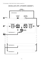
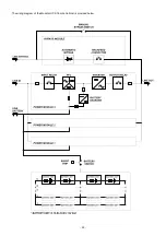
Page 20: ...20 The wiring diagram of the Modular UPS Power Cabinet is provided below...
Page 23: ...23 The wiring diagram of the Modular UPS Combo Cabinet is provided below...
Page 54: ...54 Combo Cabinet...
Page 55: ...55 Battery Cabinet...
Page 82: ......
Page 83: ......
Page 84: ...0MNMPWK25R1ENUA...

