‐
35
‐
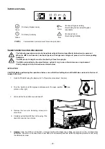
EXTRACTION
PRIOR TO THE EXTRACTION OF A BU ENSURE THAT THE SYSTEM IS NOT ON BATTERY MODE!
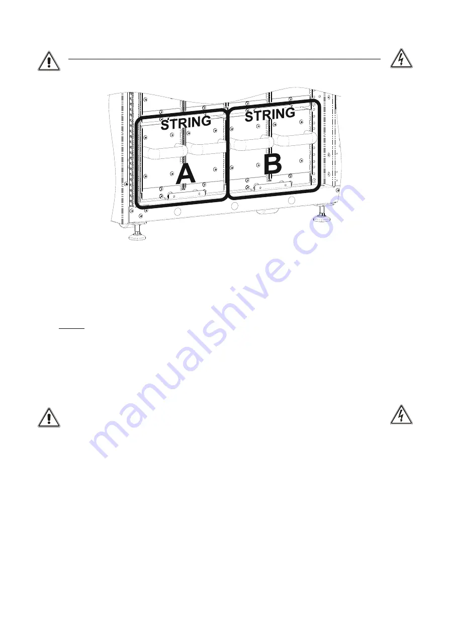
NOTE: when a BU is replaced, you must replace the other BU within the same A or B string.
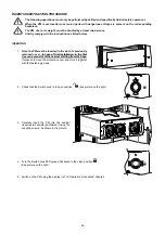
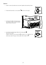
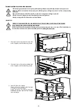
To extract the BU from the cabinet, reverse the procedure described above. In brief:
1.
Ensure that the SYSTEM IS NOT ON BATTERY MODE
2. If present, remove the locking bracket and store it together with the fastening screws.
3. Carefully extract the BU from its housing. This operation requires two persons.
4.
Caution
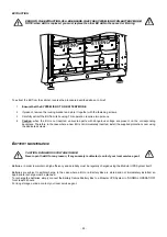
: when the BU is not inserted, uncovered parts with dangerous voltage are present on the corresponding
backplane. Therefore, in the case where a new BU is not immediately inserted, install the supplied protection cover using
the dedicated screws.
B
ATTERY MAINTENANCE
CAUTION: DANGEROUS VOLTAGE INSIDE!
Never open the BU for any reason, if any anomaly is detected, contact your local service agent.
Batteries, in order to maintain a high efficiency and durability must be regularly charged using the Modular UPS System itself.
Batteries are subject to self-discharge. In the case where a BU or a Battery Box are stored and not immediately installed, an
appropriate recharge must be planned.
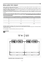
To recharge the batteries, simply connect the Battery Cabinet/Battery Box to a Modular UPS System in “NORMAL OPERATION”
for at least 24 hours.
For long storage periods, contact your local service agent.
Summary of Contents for multipower BTC 170
Page 1: ......
Page 2: ......
Page 6: ...6...
Page 8: ...8 GENERAL VIEWS Front view Back view Frame Handle with lock Door Back Panel...
Page 20: ...20 The wiring diagram of the Modular UPS Power Cabinet is provided below...
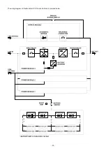
Page 23: ...23 The wiring diagram of the Modular UPS Combo Cabinet is provided below...
Page 54: ...54 Combo Cabinet...
Page 55: ...55 Battery Cabinet...
Page 82: ......
Page 83: ......
Page 84: ...0MNMPWK25R1ENUA...

