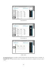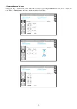
‐
36
‐
DISPLAY
O
VERVIEW
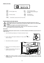
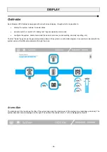
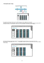
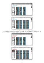
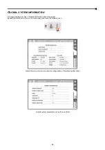
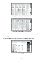
Each Modular UPS Cabinet is equipped with a touch screen display, through which it is possible to:
display the system / cabinet / module status;
activate switch on / switch off / battery test / bypass operation commands;
configure the system, access levels and the network services (e-mail sending, anomaly reporting, etc.).
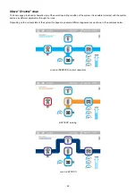
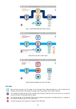
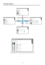
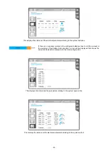
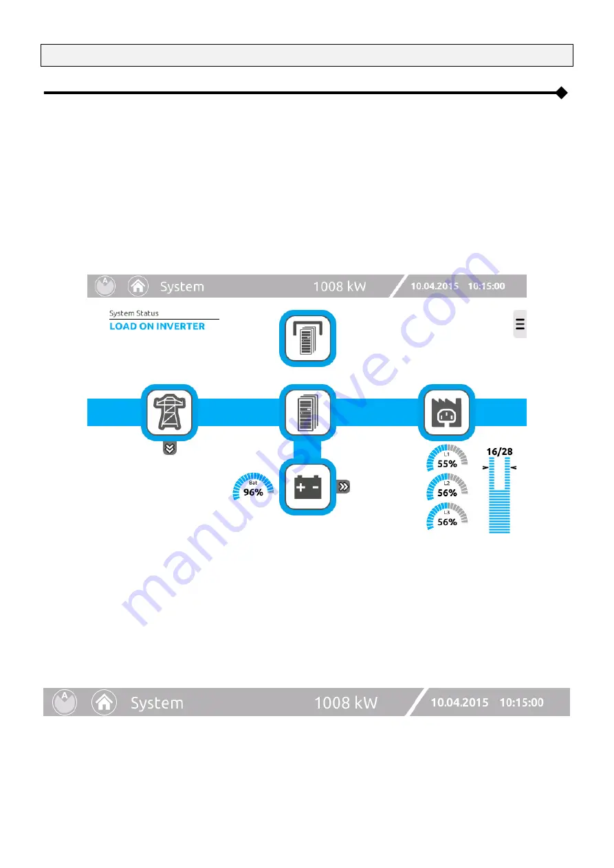
The first "Home" page shows the general operation status of the system in a schematic diagram. It is possible to interact with the
system and see the different parameters through the icons.
S
TATUS
B
AR
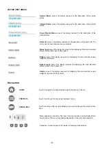
The status bar at the top shows the title of the current page and the rated power of the system (any redundancy included). The
system date and time are displayed on the right. The name of the cabinet (A, B, C or D) is displayed on the left.
Summary of Contents for multipower BTC 170
Page 1: ......
Page 2: ......
Page 6: ...6...
Page 8: ...8 GENERAL VIEWS Front view Back view Frame Handle with lock Door Back Panel...
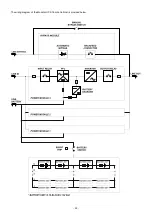
Page 20: ...20 The wiring diagram of the Modular UPS Power Cabinet is provided below...
Page 23: ...23 The wiring diagram of the Modular UPS Combo Cabinet is provided below...
Page 54: ...54 Combo Cabinet...
Page 55: ...55 Battery Cabinet...
Page 82: ......
Page 83: ......
Page 84: ...0MNMPWK25R1ENUA...

