‐
43
‐
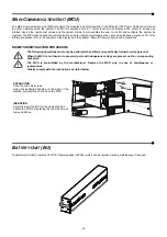
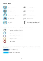
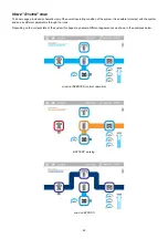
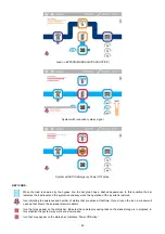
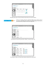
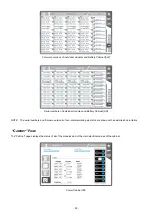
Load on BYPASS (MANUAL BYPASS ACTIVE)
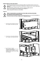
System with redundancy alarm signal
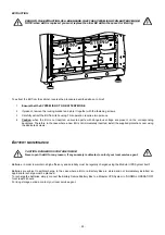
System with EPO (Emergency Power Off) active
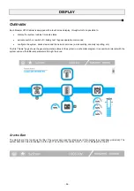
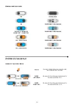
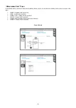
KEY ICONS:
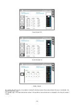
When the load is powered by the bypass line, the bar graph has a dashed appearance. In this condition the bar
indicates the load level and the system redundancy when the operation of the inverter is restored.
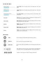
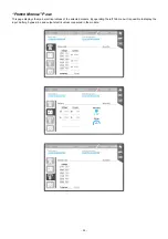
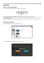
Icon indicating the existence and number of alarms that are active at that time. If you click on the icon, a window will
open up that shows the individual alarms in detail.
Icon that may appear on the status bar. Indicates that a data processing task on the mass storage is in progress; in
this condition the system may work at a slower pace.
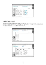
Icon that may appear on the status bar. Indicates “Power Off Active”.
Summary of Contents for multipower BTC 170
Page 1: ......
Page 2: ......
Page 6: ...6...
Page 8: ...8 GENERAL VIEWS Front view Back view Frame Handle with lock Door Back Panel...
Page 20: ...20 The wiring diagram of the Modular UPS Power Cabinet is provided below...
Page 23: ...23 The wiring diagram of the Modular UPS Combo Cabinet is provided below...
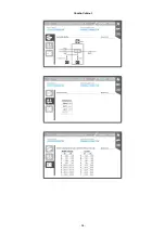
Page 54: ...54 Combo Cabinet...
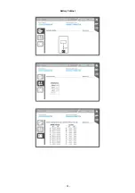
Page 55: ...55 Battery Cabinet...
Page 82: ......
Page 83: ......
Page 84: ...0MNMPWK25R1ENUA...

