‐
46
‐
“S
YSTEM
S
TATUS
”
PAGE
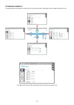
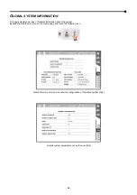
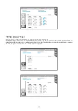
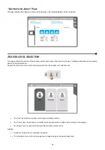
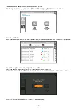
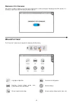
The page shown below may contain up to four TABs depending on the configuration of the system.
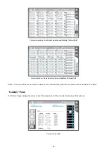
The first TAB represents the total number of Power or Combo cabinets which are present within the system; by pressing each of
the related icons (A, B, C, D) all details in relation to each of the cabinets can be monitored (“Cabinet” page)
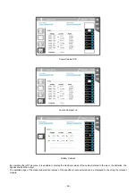
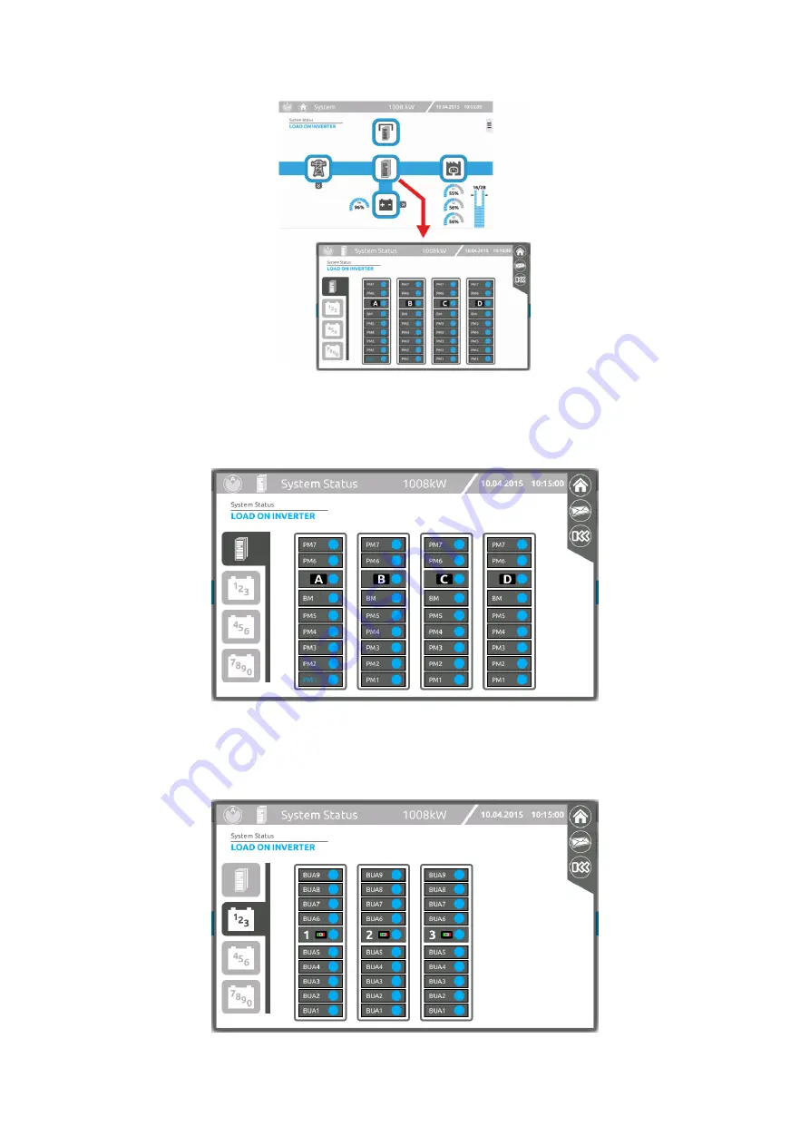
The following TABs represent the total number of connected Battery Cabinets (these are shown in groups of 3 or 4).
By pressing each of the related icons (1, 2, 3, …, 0) all details in relation to each of the cabinets can be monitored (“Battery
Cabinet” page)
Summary of Contents for multipower BTC 170
Page 1: ......
Page 2: ......
Page 6: ...6...
Page 8: ...8 GENERAL VIEWS Front view Back view Frame Handle with lock Door Back Panel...
Page 20: ...20 The wiring diagram of the Modular UPS Power Cabinet is provided below...
Page 23: ...23 The wiring diagram of the Modular UPS Combo Cabinet is provided below...
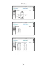
Page 54: ...54 Combo Cabinet...
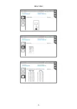
Page 55: ...55 Battery Cabinet...
Page 82: ......
Page 83: ......
Page 84: ...0MNMPWK25R1ENUA...

