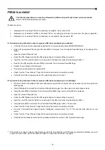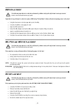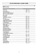
‐
70
‐
OPERATIVE PROCEDURES
Before any attempt to put the system online it is mandatory to check the power supply and connections
(PHASE, NEUTRAL, BATTERY).
Refer to the Installation Manual.
S
YSTEM
O
N COMMAND
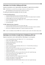
Operations to be performed in order to Switch On the MPW.
The MPW can be switched to “Normal Operation” in two ways:
A. SYSTEM ON: DIRECT COMMAND
Switch on the Mains and Bypass Input lines.
The system will turn in “Stand By” (The Leds on PSU1 and PSU2 will be lit).
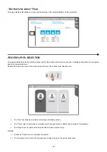
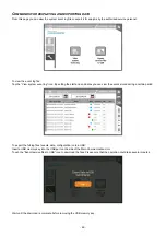
Verify the Mains and Bypass input voltages on the “System Status” page.
Verify that no anomalies are present on the “System Status” page (except the alarm for “Batteries not present”).
Verify that all the configured PMs are ready (the red led “ALARM” blinks slowly).
Verify that all the configured BM are ready (the green led “BYPASS READY” is lit fixed).
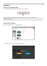
From the “Command Panel” page, slide “System Off/On” from “O” to “I” to start the System.
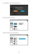
Confirm “System ON Command”.
This command will automatically Start Up the System with the following sequence:
1. PMs Precharge
2. PMs Inverters Synchronize
3. Transfer the load to the Static Bypass Line
4. Transfer the load on the Inverter Output
The “Awaiting Start Up” process will take approximately one minute.
Verify that no anomalies are present on the “System Status” page.
Verify that the measures of inverter voltages are correct and the system status is “Load on Inverter”.
Connect the batteries to the system.
Check the batteries status and verify the measures.
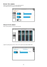
From the “Command Panel” page slide the “Battery Test” from “O” to “I” to execute the test.
Verify that the Alarm “Batteries Not Present” is not present anymore.
The System is in normal operation.
Summary of Contents for multipower BTC 170
Page 1: ......
Page 2: ......
Page 6: ...6...
Page 8: ...8 GENERAL VIEWS Front view Back view Frame Handle with lock Door Back Panel...
Page 20: ...20 The wiring diagram of the Modular UPS Power Cabinet is provided below...
Page 23: ...23 The wiring diagram of the Modular UPS Combo Cabinet is provided below...
Page 54: ...54 Combo Cabinet...
Page 55: ...55 Battery Cabinet...
Page 82: ......
Page 83: ......
Page 84: ...0MNMPWK25R1ENUA...

