4499
6
GB
4.
INSTALLATION
THE BURNER MUST BE INSTALLED IN CONFORMITY WITH LEGISLATION AND LOCAL STANDARDS.
4.1
FIXING THE BURNER TO THE BOILER
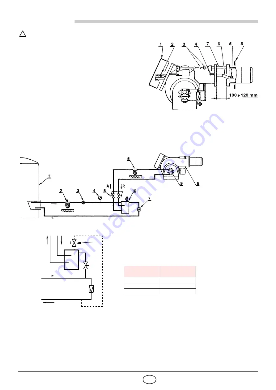
To detach the burner from the cast-iron nozzle, proceed as fol-
lows:
-
Remove the cover (1), the split pin and the pin (2), the
stops (3) and the screws (4).
-
Slide off the nozzle from the burner about 100 - 120 mm,
unhook the driving fork of the head (6) by removing the
split pins (5).
-
Now the nozzle can be completely removed from the
pins (7).
-
Fix the nozzle to the boiler by inserting the insulating gas-
ket (8).
-
Once the preselected nozzle is installed, fit the burner on
the pins (7) and leave it open about 100 - 120 mm.
-
Refit the fork (6) by hooking it to the split pins (5).
-
Lock the burner well by fixing it with the screws (4), fit the stops (3), the pin and the split pin (2).
Opening the burner for maintenance
- Repeat the operations above but do not remove the nuts (3).
Lift the burner with hooks in order to fix it to the boiler without separating it from the cast-iron nozzle.
4.2
FUEL OIL SUPPLY LINE
!
Fig. 5
D1996
D3720
1
1
- Tank (heated for heavy oil)
2
- Filter (with resistance for oil > 7°E / 50°C)
3
- Forwarding pump
4
- Control pressure gauge
5
- (Two) gate valves excluding the burner
6
- Burner
7
- Pressure regulator (see table)
8
- Filter (with resistance for oil > 7°E / 50°C)
9
- Burner pump
10
- Degassing unit
MODIFICATION FOR BYPASSED SUPPLY
The degassing unit for heavy oil must have a code
3010050
heater
fitted.
If a degassing return pipe is connected to the tank (dotted line) it is nec-
essary to partially open the manually-operated valve (1) so that the steam
can flow out.
Heavy oil
temperature °C
Pressure
bar
80
1
90
1.5
100
2
To burner
Supply
line
WARNING
• The oil could easily flow through the pipes if these are properly seized, protected and heated (by electricity, steam or hot water).
• In order to minimise gas or steam formation the oil pressure in the degassing unit (10) must be adjusted according to the supply
temperature following the table above.
• The forwarding pump capacity should have an output at the least 1.5 times bigger than that of the burner pump.
If several burners are supplied through the same ring supply line, the forwarding pump should ensure a capacity approx. 30%
more than the sum of the single burners outputs.
•
For start-up:
after excluding the burner through the gate valves (5), let the oil flow into the supply ring.
After that open the valves and supply normally the burner.
Fig. 6
Fig. 7
Summary of Contents for P 140 P/NA
Page 37: ...19 2544499 Appendice Schema quadro elettrico Appendix Electrical panel layout...
Page 38: ...2544499 20 Appendice Schema quadro elettrico Appendix Electrical panel layout...
Page 39: ...21 2544499 Appendice Schema quadro elettrico Appendix Electrical panel layout...
Page 40: ...2544499 22 Appendice Schema quadro elettrico Appendix Electrical panel layout...
Page 41: ...23 2544499 Appendice Schema quadro elettrico Appendix Electrical panel layout...
Page 43: ...25 2544499 Appendice Schema quadro elettrico Appendix Electrical panel layout...
Page 44: ...2544499 26 Appendice Schema quadro elettrico Appendix Electrical panel layout...
Page 45: ...27 2544499 Appendice Schema quadro elettrico Appendix Electrical panel layout...
Page 46: ...2544499 28 Appendice Schema quadro elettrico Appendix Electrical panel layout...
Page 47: ...29 2544499 Appendice Schema quadro elettrico Appendix Electrical panel layout...
Page 50: ......
Page 51: ......


