background image

6192

1

I

INDICE

1.

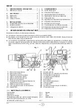
DESCRIZIONE DEL BRUCIATORE

Bruciatore di nafta con funzionamento bistadio.


1.

DESCRIZIONE DEL BRUCIATORE . . . . . . 1

1.1

Materiale a corredo  . . . . . . . . . . . . . . . . . . 1

2.

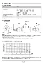
DATI TECNICI . . . . . . . . . . . . . . . . . . . . . . 2

2.1

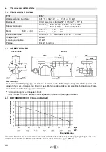
Dati tecnici . . . . . . . . . . . . . . . . . . . . . . . . . 2

2.2

Dimensioni . . . . . . . . . . . . . . . . . . . . . . . . . 2

2.3

Campo di lavoro . . . . . . . . . . . . . . . . . . . . . 2

3.

INSTALLAZIONE . . . . . . . . . . . . . . . . . . . . 3

3.1

Impianti alimentazione olio combustibile . . . . 3

3.2

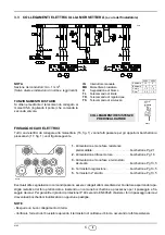
Impianto elettrico . . . . . . . . . . . . . . . . . . . . 4

3.3

Collegamenti elettrici . . . . . . . . . . . . . . . . . 5

4.

FUNZIONAMENTO . . . . . . . . . . . . . . . . . .  6

4.1

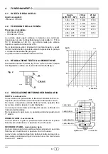
Scelta degli ugelli  . . . . . . . . . . . . . . . . . . .  6

4.2

Pressione della pompa  . . . . . . . . . . . . . . .  6

4.3

Regolazione testa di combustione. . . . . . . . .  6

4.4

Regolazione motorino serranda aria . . . . . . .  6

4.5

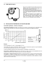
Pressostato aria  . . . . . . . . . . . . . . . . . . . . . . . .7

4.6

Regolazione temperatura di polverizzazione  .  7

4.7

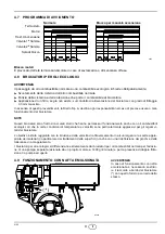
Programma di avviamento  . . . . . . . . . . . . . .  9

4.8

Bruciatori per oli ecologici . . . . . . . . . . . . . . .  9

4.9

Funzionamento con nafta emulsionata . . . . .  9

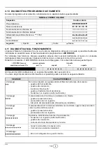
4.10 Diagnostica programma di avviamento . . . .  10
4.11 Diagnostica mal funzionamento  . . . . . . . . .  10

2893

Il bruciatore risponde al grado di protezione IP 40 secondo EN 60529.

Bruciatore con marcatura CE in conformità alle Direttive CEE: EMC 2014/30/UE, Bassa Tensione

2014/35/UE e Macchine 2006/42/CE.

In conformità con la EN 267, l’applicazione del bruciatore alla caldaia, la regolazione e il collaudo, devo-

no essere eseguiti nell’osservanza del manuale d’istruzione della caldaia stessa, compreso il controllo
della concentrazione di CO e CO

2

 nei fumi, della loro temperatura e di quella media dell’acqua della cal-

daia. 

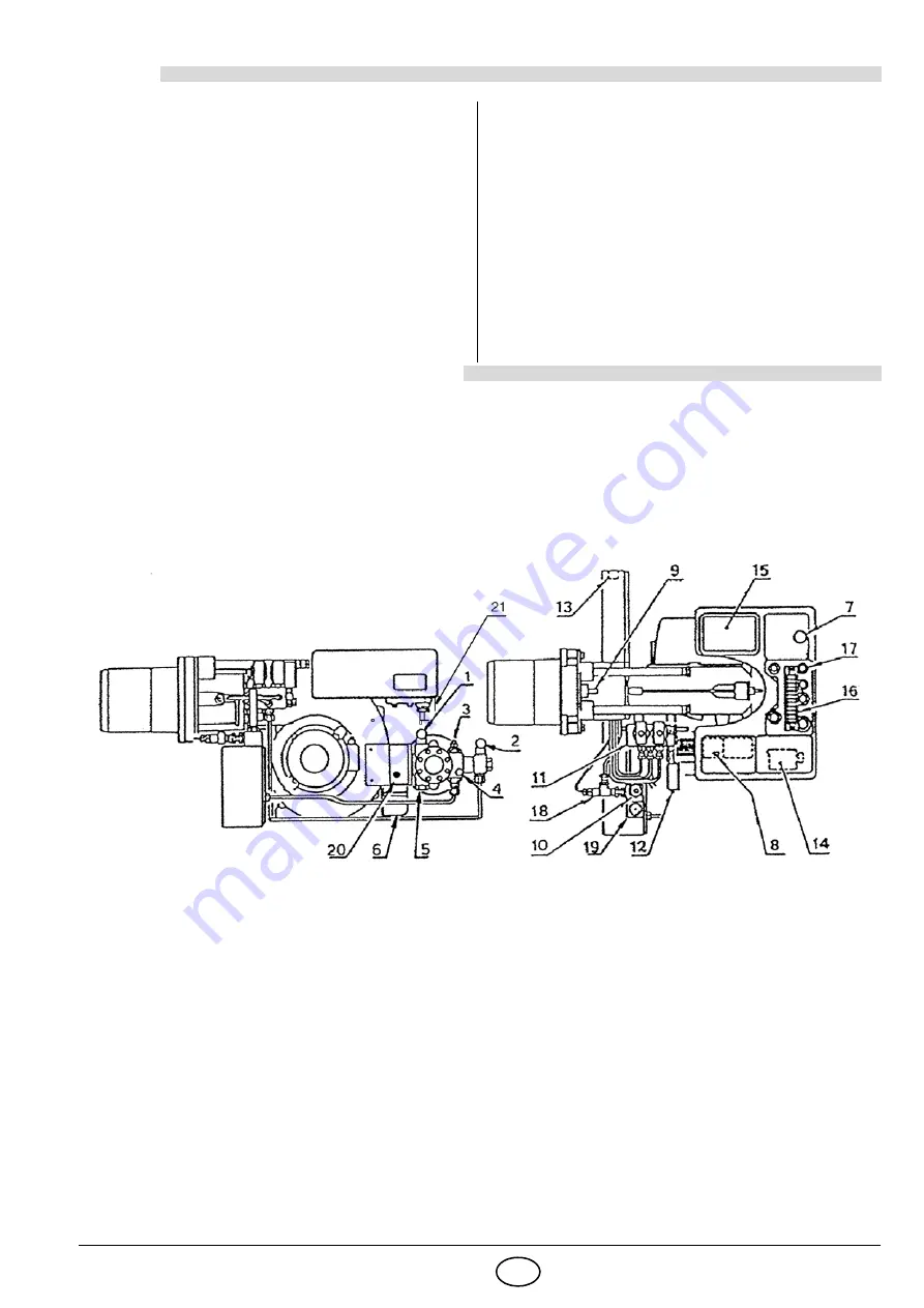
  1

- Raccordo di aspirazione

  2

- Raccordo di ritorno

  3

- Regolatore pressione pompa

  4

- Attacco manometro (G1/8) 

  5

- Attacco vacuometro (G1/2)

  6

- Motorino apriserranda

  7

- Pulsante di sblocco apparecchiatura con 

segnalazione di blocco

  8

- Sblocco salvamotore ventilatore 

  9

- Vite regolazione testa di combustione

10

- Doppio filtro

11

- Gruppo valvole

12

- Manometro con rubinetto di protezione

13

- Termostato di regolazione

14

- Contattore preriscaldatore

15

- Trasformatore

16

- Morsettiera

17

- Bocchettoni pressacavo

18

- Valvola antigas

19

- Termometro

20

- Avviatore motore pompa con sblocco

21

- Pressostato aria

Fig. 1

1.1

MATERIALE A CORREDO

Tubi flessibili  . . . . . . . . . . . . . . . . . . . . . . . . . . . . . .  N° 2

Nipples  . . . . . . . . . . . . . . . . . . . . . . . . N° 2

Guarnizioni  . . . . . . . . . . . . . . . . . . . . . . . . . . . . . . .  N° 2

Viti. . . . . . . . . . . . . . . . . . . . . . . . . . . . N° 4

Schermo per flangia . . . . . . . . . . . . . . . . . . . . . . . . .  N° 1

Ugelli . . . . . . . . . . . . . . . . . . . . . . . . . . N° 2

Prolunghe per guide (per versione testa allungata) . .  N° 2

Guarnizione  . . . . . . . . . . . . . . . . . . . . N° 1

Raccordo per funzionamento con nafta
emulsionata (vedere pag. 9)  . . . . . . . . . . . . . . . . . .  N° 1

Summary of Contents for PRESS 30 N/ECO

Page 1: ...ni per installazione uso e manutenzione Bruciatore di nafta Heiz lbrenner Heavy oil burner Br leur fioul lourd CODICE CODE MODELLO MODELL MODELE MODEL TIPO TYP TYPE 3433823 PRESS 30 N ECO 626 T 343382...

Page 2: ......

Page 3: ...CE In conformit con la EN 267 l applicazione del bruciatore alla caldaia la regolazione e il collaudo devo no essere eseguiti nell osservanza del manuale d istruzione della caldaia stessa compreso il...

Page 4: ...1 kW Pompa 60 kg h a 20 bar D2715 D2628 Bruciatore Piastra caldaia NOTA Il peso del gruppo pompante nella parte posteriore sollecita a flessione le guide si consiglia di sostenere il bruciatore in fa...

Page 5: ...ano a perfetta tenuta Quando la cisterna ad un livello inferiore del bruciatore si consiglia di far arrivare la tubazione alla stessa al tezza della tubazione di aspirazione In questo caso non necessa...

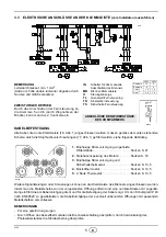
Page 6: ...mpa CMV Contattore motore ventilatore CR Contattore preriscaldatore F Soppressore FR Fotoresistenza MB Morsettiera bruciatore MP Motore pompa MV Motore ventilatore PA Pressostato aria R1 Resistenza po...

Page 7: ...di terra Verificare l arresto del bruciatore aprendo il termostato di caldaia e il blocco oscurando la fotoresistenza IN Interruttore manuale MB Morsettiera bruciatore H Segnalazione di blocco TL Tele...

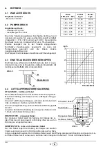
Page 8: ...icalmente e cor risponde alla condizione di serranda aria totalmente chiusa Per avere un apertura parziale della serranda spostare tale leva verso sinistra segno sulla targhetta La nuova posizione del...

Page 9: ...massima disinserisce le resistenze quando a causa di un avaria del termostato di regolazione si registra un sensibile aumento della temperatura nel preriscaldatore In caso di interventi anomali accer...

Page 10: ...datore bisogna preriscaldare il combustibile per almeno 30 mi nuti prima di accendere il bruciatore In caso contrario provvedere ad alimentare la resistenza sul portaspruz zo con una linea monofase in...

Page 11: ...mbustibili ecologici oli che in certe condizioni di temperatura e velocit sono particolarmente aggressivi per gli organi vi tali del bruciatore L obiettivo stato raggiunto con la riduzione della veloc...

Page 12: ...fiamma debole Alimentazione elettrica inferiore a 170V Blocco Luce estranea Legenda Spento Giallo Verde Rosso SEGNALE CAUSA PROBABILE 2 lampeggi Non viene rilevato un segnale stabile di fiamma nel tem...

Page 13: ...r Anbau des Brenners an den Heizkessel Regulierung und Pr fung unter Beachtung des Bedienungshandbuches des Heizkessels ausgef hrt werden Dies schliesst die Kon trolle von CO und CO2 Gehalt im Rauch d...

Page 14: ...h bei 20 bar D2715 D2628 Brenner Kesselplatte BEMERKUNG Das Gewicht der Pumpengruppe im hinteren Teil kann durch die Beanspruchung zum Verbiegen der F h rungen f hren es ist ratsam den Brenner beim En...

Page 15: ...un gen wird empfohlen Wenn der Tank tiefer als der Brenner angebracht ist empfehlen wir die Leitungen des Tankes in gleicher H he wie die der Saugleitung enden zu lassen In diesem Fall ist ein Fussven...

Page 16: ...tgeber Pumpenmotor CMV Kontaktgeber Gebl semotor CR Kontaktgeber der Heizwiderstande F Funkentst rer FR Fotowiderstand MB Brenner Klemmleiste MP Pumpenmotor MV Gebl semotor PA Luftdruckw chter R1 Wide...

Page 17: ...Erdung sorgen Durch ffnen des Kesselthermostaten die Brennerabschaltung berpr fen durch Verdunkelung des Photowiderstandes die St rabschaltung berpr fen IN Schalter f r das manuelle Ausschalten des B...

Page 18: ...ebels ist die Luftklappe v llig ge schlossen Um eine Teil ffnung der Klappe zu erhalten den Hebel nach links verstellen Zeichen auf dem Schild Die neue Klappenstellung kann bei Brennerstillstand gepr...

Page 19: ...t der max Temperatur schaltet den Widerstand aus wenn im Vorw rmer auf Grund einer Fehlfunktion des Einstellthermostates eine sp rbare Temperaturerh hung festgestellt wird Bei anomalen Einstellungen n...

Page 20: ...uss der Brennstoff f r mindestens 30 Minuten erw rmt werden bevor man den Brenner einschaltet Anderenfalls muss der Widerstand am D senstock mit einer un abh ngigen Monophasenleitung gespeist werden w...

Page 21: ...erm glicht haben le die bei bestimmten Temperatur und Geschwindigkeitsbedingungen besonders aggressiv f r die lebens wichtigen Organe des Brenners sind Dieses Ziel wurde durch eine Verringerung der Du...

Page 22: ...Stromversorgung unter 170V St rabschaltung Fremdlicht Erl uterung Aus Gelb Gr n Rot Signal M GLICHE URSACHE 2 maliges Blinken Innerhalb der Sicherheitszeit wird keine stabile Flamme festgestellt Defe...

Page 23: ...conformity with the EN 267 the application of the burner to the boiler adjustment and testing must be carried out in compliance with the said boiler s instruction manual including the checking of the...

Page 24: ...wer 4 1 kW Pump 60 kg h at 20 bar D2715 D2628 Burner Boiler plate NOTE The weight of the rear part of the pumping assembly exerts flexure stress on the guides you are advised to hold the burner while...

Page 25: ...ed at the vacuometer fitting 5 fig 1 The pipes should be perfectly airtight When the tank is placed below of the burn er level the return pipe should arrive at the same level as the suction pipe In th...

Page 26: ...P CMV CMP Pump motor contact maker CMV Fan motor contact maker CR Pre heater contact maker F Suppressor FR photocell MB Burner terminal strip MP Pump motor MV Fan motor PA Air pressure switch R1 Spray...

Page 27: ...by opening the boiler thermostat and the burner lock out by darkening the photocell IN Manual switch MB Burner terminal strip H Lock out signal TL Limit remote control TR Adjustment remote control TS...

Page 28: ...corre sponds to the air damper fully closed A partial opening of the air damper might be obtained by moving this lever leftwards on the plate The new position of the air damper is detectable when the...

Page 29: ...m value contact thermostat switches off the resistors when in case of failure of the adjustment thermostat the temperature increases inside the pre heater In case of abnormal cut ins check the control...

Page 30: ...eater line be turned off the fuel must be pre heated for approximately 30 minutes before the burner start up On the contrary the nozzle holder resistor must be supplied with an independent single phas...

Page 31: ...ecological fuels as well oils that in certain temperature and speed conditions are particularly aggressive for the vital parts of the burner The objective has been achieved with the reduction of the t...

Page 32: ...with flame ok Operation with weak flame Electrical supply lower than 170V Lock out Extraneous light Key Off Yellow Green Red SIGNAL PROBABLE CAUSE 2 blinks No stable flame is detected in the safety t...

Page 33: ...CE Conform ment la EN 267 l application du br leur la chaudi re le r glage et l essai doivent tre ef fectu s en respectant les instructions du manuel d instruction de la chaudi re y compris le contr l...

Page 34: ...orb e 4 1 kW Pompe 60 kg h 20 bars D2715 D2628 Br leur Plaque chaudi re NOTE Le poids du groupe de pompage arri re provoque la courbure des glissi res il est conseill de soutenir le br leur pendant l...

Page 35: ...teries doivent tre parfaitement tanches Si la citerne est un niveau in f rieur par rapport celui du br leur il est conseill de ramener la tuyauterie au m me niveau que celle d aspiration Dans ce cas l...

Page 36: ...eur pompe CMV Contacteur moteur ventilateur CR Contacteur pr chauffeur F Suppresseur FR Cellule photor sistance MB Bornier br leur MP Moteur pompe MV Moteur ventilateur PA Pressostat air R1 R sistance...

Page 37: ...du br leur en ouvrant le thermostat de chaudi re et la mise en s curit en obscurcissant la cellule photor sistance IN Interrupteur manuel MB Bornier br leur H Signalisation de blocage TL T l commande...

Page 38: ...respond la position du volet d air totalement ferm Pour avoir une ouverture partielle du volet d air d placer le levier vers la gauche signe sur l tiquette La nouvelle position du volet peut tre contr...

Page 39: ...e apr s une panne du thermostat de r glage on constate une augmentation sensible de la temp rature dans le pr chauffeur S il y a des interventions anomales contr ler le bon fonctionnement du thermosta...

Page 40: ...le fioul pendant 30 minutes au moins avant l allumage du br leur Dans le cas contraire il faut alimenter la r sistance sur le portegicleur par l interm diaire d une ligne monophas e ind pendante prot...

Page 41: ...iles colo giques dans certaines conditions de temp rature et de vitesse ces huiles sont particuli rement nocives pour les organes vitaux du br leur Pour viter ces inconv nients on a r duit la vitesse...

Page 42: ...me faible Alimentation lectrique inf rieure 170V Blocage Lumi re trang re L gende teint Jaune Vert Rouge SIGNAL CAUSE PROBABLE 2 clignotements Un signal stable de flamme n est pas d tect durant le tem...

Page 43: ......

Page 44: ...Con riserva di modifiche nderungen vorbehalten Subject to modifications Sous r serve de modifications RIELLO S p A I 37045 Legnago VR Tel 39 0442 630111 http www riello it http www riello com...

Reviews: