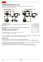
13
2902936
GB
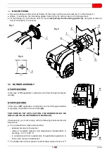
4.5 AIR ADJUSTMENT,
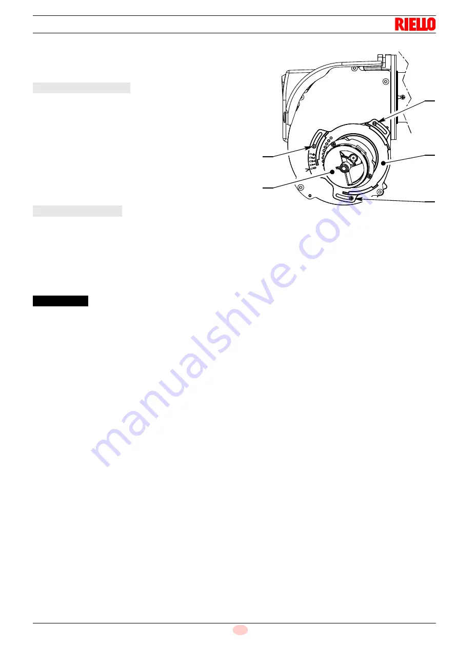
(fig. 19)
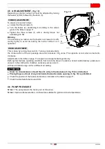
Depending on burner output, air must be adjusted by turning
the feeder (2) first, followed by the knob (3).
To adjust, proceed as follows:
➤
Loosen the three screws (1).
➤
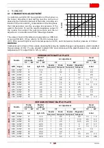
Turn the feeder (2), positioning it according to the values
given in the table on page 11.
➤
Tighten the three screws (1) with a driving torque not
exceeding 0.8 Nm.
Warning
It is essential you make sure the feeder is screwed on suffi-
ciently tightly to avoid de-setting the burner while it is in
operation.
This is done by turning the knob (3). Turning clockwise limits
the cross-section of the air passage area and increases CO
2
value. The opposite occurs when turned anti-
clockwise.
Adjustments in the table on page 11 are given as an approximate guide only.
Each system features operating conditions that cannot be known in advance: actual nozzle delivery, pressure or
vacuum in the combustion chamber, necessary excess air etc...
All these conditions may call for a different air setting.
➤
Under no circumstances should the air's entry in the knob area (3, fig. 19) be obstructed.
➤
Placing fingers or tools of any kind inside the knob’s intake opening (3, fig. 19) is prohibited.
➤
Check the position of the feeder and knob as indicated in the table on page 11.
➤
Check the Bacharach device and CO
2
.
4.6 PUMP PRESSURE
12 bar: The pump leaves the factory set at this value.
14 bar: Improves flame retention; it is therefore suitable for ignitions at low temperatures.
Fig. 19
D7004
1
1
1
2
3
FEEDER ADJUSTMENT
KNOB ADJUSTMENT
ATTENTION


