20115639
16
GB
Start-up, calibration and operation of the burner
7.5
Air damper adjustment
The air damper is adjusted in the factory.
This adjustment is purely indicative. However, each installation
has its own operating conditions: nozzle flow rate, positive or
negative pressure in the combustion chamber, air excess re-
quirement, etc. All these conditions can require different adjust-
ments of the air damper.
7.5.1
Main air damper
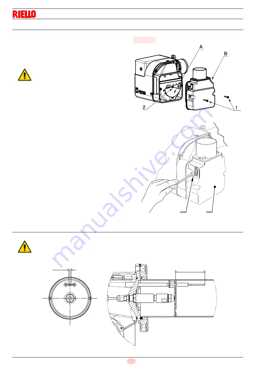
The main air damper A)(Fig. 13) can be regulated in position B)
for the burner code 20105295.
To adjust the positions of the air damper, proceed as follows:
remove the secondary damper B) by loosening the screw 1);
loosen the screw 2) and turn the main damper A) to the
required position;
tighten the screw 2) and re-install the secondary damper B).
7.5.2
Two-stage air damper
The purpose of the damper B)(Fig. 14) is to optimise the air in-
take.
Optimisation is possible by using the screw 3)(Fig. 14).
7.6
Electrodes setting
WARNING
Only for code 20105295
The adjustment of the air is carried out using two
independent dampers (Fig. 13).
Fig. 13
20093890
20105295
B
3
E9172
Fig. 14
WARNING
These dimensions Fig. 15 must be respected.
± 0 . 5
5
± 0 . 5
6 3
Fig. 15
20116946


