7
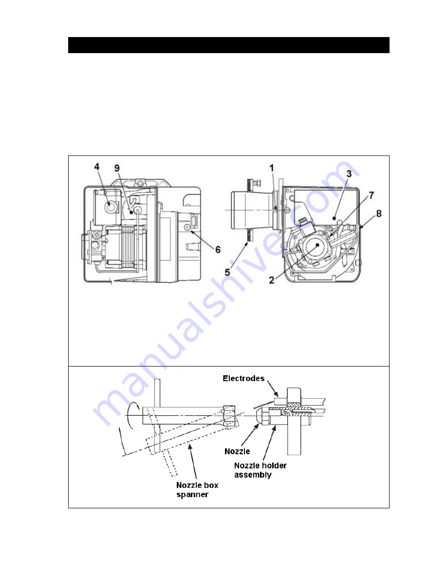
1. Switch off the electrical supply to the burner
and isolate the oil supply.
2. Remove the burner plug from the boiler
control box.
3. Remove the burner from the boiler (
fig 8
).
4. Remove the blast tube (
fig 5
), exposing the
nozzle holder assembly.
5. Taking care not to damage the electrodes,
remove the nozzle with an appropriate
socket or box spanner (
fig 6
)
6. Fit a new nozzle of the same specification.
7. Replace the flame ring in the same position,
check the electrode positions (
fig 7
) and
tighten.
8. Refit the blast tube.
Fig 5
Fig 6
NOZZLE REPLACEMENT
1
– Blast tube retaining screws (x2)
2
– Oil pump
3
– Control box
4
– Reset button / light
5
– Mounting flange / gasket
6
– Air damper fine tuning
7
– Pump pressure adjustment
8
– Pressure gauge connection
9
– Photocell
Summary of Contents for RDB2
Page 11: ...11 Fig 11 Burner Fault finding Logic Chart ...
Page 13: ...13 Fig 12 ...


