6
OIL PUMP
If the burner goes to a lockout state due to a lack of oil pressure, the pump may require priming. Remove
the pressure gauge bleed port plug until oil is seen to be present and replace the plug.
Single-pipe systems
Where the lowermost part of the tank is above the level of the oil pump, a single-pipe gravity system can
be used. The supply pipe should be connected to the suction port on the burner pump via the flexible hose
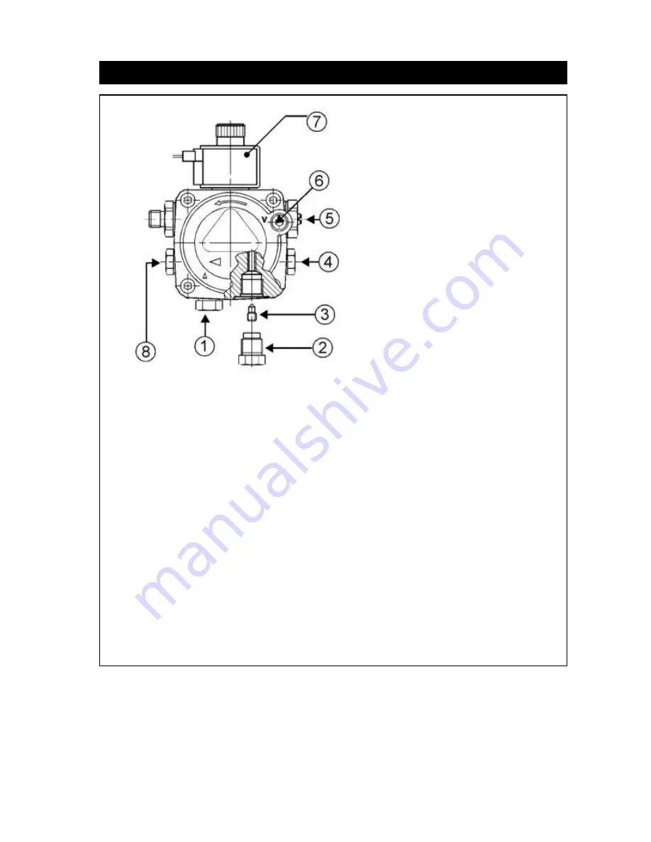
(supplied). The pump is pre-set to run on single-pipe oil supplies the bypass screw (
3
) must not be present
in the return line (see
fig 4
).
Two-pipe systems
Where the lowermost part of the tank is below the level of the burner, a two-pipe suction lift is necessary. A
second flexible hose will be required, and the oil pump must first be converted for use. Remove the return
line plug (
2
), insert the bypass screw (
3
) and connect a second flexible oil line (not supplied).
Single pipe oil supplies with a de-aerator
Where a two-pipe suction lift is required, but it is not feasible to fit a return pipe, an oil de-aerator can be
used. The burner should be piped and the pump converted as for a two-pipe system, up to the de-aerator,
at which point a single pipe can be taken to the storage tank. The de-aerator should be fitted as close to
the boiler as possible though externally to the premises at a height no lower than the oil pump.
Fig 4
1
– Suction line
2
– Return line
3
– Bypass screw
4
– Pressure gauge connection /
air bleed point
5
– Pressure adjustment
6
– Suction gauge connection
7
– Solenoid valve
8
– Auxiliary pressure test point
Summary of Contents for RDB3
Page 11: ...11 Fig 11 Burner Fault finding Logic Chart ...
Page 13: ...13 Fig 12 ...


