background image

2902862 (4) - 03/2012

Montage und Bedienungsanleitung
Installation, use and maintenance instructions
Instrucciones de instalación, montaje y funcionamiento

Öl-Gebläsebrenner
Light oil burners
Quemadores de gasóleo

Einstufiger Betrieb
One stage operation
Funcionamiento de una sola llama

CODE - CÓDIGO

MODELL - MODEL

MODELO

TYPE - TIPO

3739370 - 3739380

RG3F

393T1

D

GB

E

Summary of Contents for RG3F

Page 1: ...nance instructions Instrucciones de instalación montaje y funcionamiento Öl Gebläsebrenner Light oil burners Quemadores de gasóleo Einstufiger Betrieb One stage operation Funcionamiento de una sola llama CODE CÓDIGO MODELL MODEL MODELO TYPE TIPO 3739370 3739380 RG3F 393T1 D GB E ...

Page 2: ...wing European Directives Council Directive 2006 95 CE relating to Electrical Equipment Council Directive 2006 42 CE relating to Machinery Council Directive 2004 108 CE relating to Electromagnetic Compatibility and to the following Technical Standards EN 267 CE Certification No 0036 0348 04 as 92 42 EEC DECLARACIÓN DE CONFORMIDAD RIELLO S p A declara bajo su responsabilidad que el quemador serie Gu...

Page 3: ...htungsschema 7 4 BETRIEB 8 4 1 Einstellung der Brennerleistung 8 4 2 Empfohlene Düsen 8 4 3 Elektrodeneinstellung 9 4 4 Pumpendruck 9 4 5 Brennkopfeinstellung 9 4 6 Luftklappeneinstellung 9 4 7 Betriebsablauf 10 5 WARTUNG 10 6 STÖRUNGEN ABHILFE 11 1 Ölpumpe 2 Steuergerät 3 Entstörtaste mit Störanzeige 4 Kesselflansch mit Isolierdichtung 5 Luftklappenregulierung 6 Düsenstock 7 Photowiderstand Abb 1...

Page 4: ...olgenden Merkmalen Funkenrückstellfunktion Nachzündungs und Rücklaufschalter Leuchtmelder LED der verschiedenen Betriebsphasen grüne Led Motorbetrieb gelbe Led Vorwärmen rote Led Nachverbrennung Steckdose für Fernentriegelung und Entriegelungsfunktion wegen nicht erfolgtem Ausschalten Für die Installation des Steuergeräts auf die ihm anliegenden Anweisungen Bezug nehmen Der Satz muss in Konformitä...

Page 5: ...m EN 746 2 für das ganze ausgerüstete Gerät vorgesehenen Genehmi gungsbedingungen für einen Betrieb mit Brennkammer auf Unterdruck bis zu 2 mbar anwendbar 228 142 300 213 160 190 12 36 285 345 1 1 99 99 127 4 5 4 5 D5353 ø 123 Heizöldurchsatz kg h Brennerleistung kW Druck im Feuerraum mbar 0 1 0 D4445 2 0 1 0 2 0 EN 267 EN 746 2 6 7 8 80 100 120 9 10 140 160 11 12 13 14 15 16 180 ...

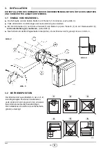
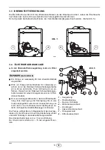
Page 6: ...en 5 und falls erforderlich den Muttern 2 den Flansch 1 an der Heizkesseltür 3 mit Isolierdichtung 4 montieren siehe Abb 2 Nach Abschluß der Montagearbeiten überprüfen ob der Brenner leicht geneigt ist wie in Abb 4 3 2 BETRIEBSPOSITION Abb 4 D5025 Abb 2 Abb 3 S7071 Der Brenner darf ausschließlich in den in 1 2 4 und 6 gezeigten Positionen funktionieren Jede andere Anordnung kann den einwand freien...

Page 7: ... der Rücklauf Schlauchleitungss topfen wieder mit einem Anzugsmoment von 0 5 Nm einzuschrauben O Es muss sichergestellt werden daß die Ölrücklaufle itung ohne Verengung und Verstopfung frei in den Tank zurückgeführt wird Durch Drukkerhöhung von mehr als Š 1 bar im Rücklauf wird die Ölpumpe un dicht mit folglichen Kraftstoffleckagen im Brenner Die Pumpe verfügt über ein Regelelement des Auslass dru...

Page 8: ...r Eintritt des Brennstoffes eine Störabschaltung erfolgen mindestens 20 Sekunden warten und da nach den Vorgang wiederholen Bei den Zweirohr Unterdruckanlagen Abb 9 empfehlen wir die Ölrücklaufleitung in gleicher Höhe wie die Saugleitung im Tank enden zu lassen Es kann auf ein Fußventil in der Saugleitung verzichtet werden Endet die Rücklaufleitung über dem Ölniveau wird auf der Saugseite zwingend...

Page 9: ...enner Erdung 552SE STEUERGERÄT PE L N 50 60Hz 220 230V NULLEITER NICHT MIT DER PHASE VERWECHSELN WICHTIGER HINWEIS ANMERKUNGEN Leiterdurchmesser min 1 mm2 Außer im Falle anderslautender Angaben durch Normen und örtliche Gesetze Die vom Installateur ausgeführten elektrischen Verbindungen müssen den lokalen Bestimmu ngen entsprechen Blau Sicherheitstemper aturbegrenzer PRÜFUNG Die Regelabschaltung d...

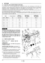
Page 10: ... en sollten die Einstellungen je nach An forderungen des Erzeugers ausgeführt werden Bei Betrieb mit 60Hz muss der Brenner neu geeicht werden wobei die Luftklappe zu schließen ist so dass die eingehende Luft menge reduziert wird 4 2 EMPFOHLENE DÜSEN Delavan typ W B Danfoss typ S B Monarch typ R Steinen typ S Q ANMERKUNG Für Düsen mit 3 00 3 50 GPH vorzugsweise Vollkegel benutzen AUSWECHSELN DER DÜ...

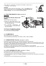
Page 11: ...ube 4 Abb 6 Seite 5 betätigen 4 5 BRENNKOPFEINSTELLUNG siehe Abb 11 Seite 8 Die Einstellung des Flammkopfs ist je nach Brennerdurchsatz unterschiedlich Sie ist vom Öldurchsatz abhängig und wird ausgeführt indem man die Einstellschraube 5 im Uhrzeigersinn oder entgegen dem Uhrzeigersinn soweit dreht bis die auf der Einstellspindel markierte Raste 9 mit der Kante am Düsenstock 1 übereinstimmt In Abb...

Page 12: ...halten WICHTIGSTE WARTUNGSARBEITEN Überprüfen ob die Ölversorgungsleitung und die Rücklaufleitung weder verstopft noch geknickt sind Filter in der Versorgungsleitung und an der Pumpe reinigen Die Reinigung des Photowiderstandes ausführen 7 Abb 1 Seite 1 Korrekten Brennstoffverbrauch überprüfen Öldüse austauschen Abb 11 S 8 und die korrekte Stellung der Elektroden überprüfen Abb 12 S 9 Brennerkopf ...

Page 13: ...edienungsanleitung und durch das Eingreifen von unbefugtem Personal verursacht werden ist ausgeschlossen STÖRUNGEN MÖGLICHE URSACHE ABHILFE Der Brenner fährt bei der Auslösung du Begrenzungsthermo stat nicht an Keine Stromzufuhr Spannung zwischen den Klemmen L1 N des 7 poligen Steckers prüfen Sicherungen überprüfen Überprüfen ob der Sicherheitstemper aturbegrenzer von Hand entriegelt wer den muss ...

Page 14: ......

Page 15: ...es 8 4 3 Electrodes adjustment 9 4 4 Pump pressure 9 4 5 Combustion head setting 9 4 6 Air damper adjustment 9 4 7 Burner start up cycle 10 5 MAINTENANCE 10 6 FAULTS SOLUTIONS 11 If the burner is to be combined with a hot air generator in Germany WLE according to DIN 4794 the con trol box must be replaced with a Riello 550 SMD control box remove the bridge and the flame sensor must be replaced wit...

Page 16: ...park reset function switch for post firing and recycle indicator LED reporting various operating stages green LED motor operating yellow LED pre heating stage red LED post combustion socket for remote reset and reset function in case of failed shutdown Refer to the instructions supplied with the control box for installation The kit must be installed in conformity with laws and local regulations RE...

Page 17: ...e combustion chamber featuring negative pressure up to 2 mbar according to the approval terms provided for in standard EN 746 2 for the whole unit com plete with equipment 228 142 300 213 160 190 12 36 285 345 1 1 99 99 127 4 5 4 5 D5353 ø 123 Light oil output kg h Thermal power kW Pressure in combustion chamber mbar 0 1 0 D4445 2 0 1 0 2 0 6 7 8 80 100 120 9 10 140 11 12 EN 267 EN 746 2 160 13 14...

Page 18: ...to the heat generator door 3 using screws 5 and if necessary the nuts 2 inter posing the insulating gasket 4 see fig 2 After installation ensure that burner is lightly inclined as in fig 4 3 2 WORKING POSITION Fig 4 D5025 Fig 2 Fig 3 S7071 The burner is designed to work only in the po sitions 1 2 4 and 6 Any other position could compromise the cor rect working of the appliance Installations 3 and ...

Page 19: ...then screw again the plug 2 with a torque of 0 5 Nm O Before starting the burner make sure that the return pipe line is not clogged An excessive back pressure Š 1 bar would cause the damage of the pump seal with subsequent fuel leaks inside the burner The pump has a delivery pressure regulation device 4 Pressure increases if turned in a clockwise direction and decreases if turned in the other dire...

Page 20: ...out occur prior to the arrival of the fuel await at least 20 seconds before repeating the operation In two pipe vacuum systems fig 9 the return line should terminate within the oil tank at the same level as the suction line In this case a non return valve is not required Should however the return line arrive over the fuel level a non return valve is required This solution is less reliable than the...

Page 21: ...lation The electrical wiring carried out by the installer must be in compliance with the rules in force in the Country WARNING DO NOT EXCHANGE NEUTRAL WITH PHASE 7 pin plug 7 pole socket Black White Capacitor Main switch T6A Motor Blue Oil valve Hour counter 230V 0 1A max Limit thermostat Remote lock out signal 230V 0 5A max Ignition electrodes Brown Burner earth 552SE CONTROL BOX Photoresistance ...

Page 22: ...ica tion to get the best performance from the burner the regulations should be made on the basis of the effective requirements of the gen erator With 60Hz power frequency the burner must be re set closing the air damper so that the amount of intake air is reduced 4 2 RECOMMENDED NOZZLES Delavan type W B Danfoss type S B Monarch type R Steinen type S Q NOTE For 3 00 3 50 GPH nozzles it is advisable...

Page 23: ... the screw 4 fig 6 page 5 4 5 COMBUSTION HEAD SETTING see fig 11 page 8 Combustion head adjustment varies depending on burner delivery It depends on the output of the burner and is carried out by rotating clockwise or counterclockwise the setting screw 5 until the set point marked on the regulating rod 9 is level with the outside plane of the nozzle holder assembly 1 Figure 11 illustrates the head...

Page 24: ...not obstructions or dents in the supply or return oil pipes Clean the filter in the oil suction line and in the pump Clean the photoresistance 7 fig 1 page 1 Check for correct fuel consumption Replace the nozzle fig 11 page 8 and check the correct position of electrodes fig 12 page 9 Clean the combustion head in the fuel exit area on the diffuser disc Leave the burner working without interruptions...

Page 25: ...the intervention of un qualified personnel FAULTS POSSIBLE CAUSES SOLUTION The burner doesn t start when the limit thermostat closes Lack of electrical supply Check presence of voltage in the L1 N clamps of the 7 pin plug Check the conditions of the fuses Check that safety thermostat is not lock out The photoresistance sees false light Eliminate the light Start thermostats are faulty Replace them ...

Page 26: ......

Page 27: ...4 2 Boquillas aconsejadas 8 4 3 Regulación de los electrodos 9 4 4 Presión de la bomba 9 4 5 Regulación cabezal de combustión 9 4 6 Regulación del registro del aire 9 4 7 Ciclo de puesta en marcha 10 5 MANTENIMIENTO 10 6 ANOMALÍAS SOLUCIONES 11 Para combinar el generador con generadores de aire caliente en Alemania WLE según DIN 4794 hay que sustituir la caja de control por la de tipo Riello 550 S...

Page 28: ...función de restablecimiento chispa interruptor para post encendido y recirculación led de señalización de las distintas etapas de funcionamiento led verde funcionamiento motor led amarillo etapa de precalentamiento led rojo poscombustión conector para rearme a distancia y función de rearme por falta de apagado Para la instalación de la caja de control refiérase a las instrucciones que la acompañan...

Page 29: ...to con cámara de combustión bajo vacío hasta 2 mbar según las condiciones de aprobación previstas por la norma EN 746 2 para el aparato entero equipado 228 142 300 213 160 190 12 36 285 345 1 1 99 99 127 4 5 4 5 D5353 ø 123 Caudal de gasóleo kg h Potencia térmica kW Presión en cámara de combustión mbar 0 1 0 2 0 1 0 2 0 EN 267 EN 746 2 D4445 6 7 8 80 100 120 9 10 140 160 11 12 13 14 15 16 180 ...

Page 30: ...ante los tornillos 5 y si es necesario las tuercas 2 interponiendo la junta aislante 4 ver fig 2 Cuando el montaje ha terminado comprobar que el quemador quede ligeramente inclinado ver fig 4 3 2 POSICIÓN DE FUNCIONAMIENTO Fig 4 D5025 Fig 2 Fig 3 S7071 El quemador está preparado exclusivamente para el funcionamiento en las posiciones 1 2 4 y 6 Otra posición se debe considerar comprome tente para e...

Page 31: ... 2 con par de torsión 0 5 Nm O Antes de poner en funcionamiento el quemador hay que asegurarse de que el tubo de retorno del combus tible no esté obstruido Una contrapresión excesiva Š 1 bar causaría la rotura del órgano de estan quidad de la bomba con consiguientes pérdidas de combustible adentro del quemador La bomba dispone de un regulador de la presión de im pulsión 4 La presión aumenta giránd...

Page 32: ...rar el cebado Si la acción de seguridad se produce antes de la llegada del combustible esperar como mínimo 20 segun dos y luego iniciar de nuevo esta operación En las instalaciones por depresión de dos tubos fig 9 la tubería de retorno debe llegar a la misma altura que la de aspiración En este caso no se necesita válvula de pie De lo contrario la válvula es indis pensable Esta solución es menos fi...

Page 33: ... y el hilo de tierra Cuando se vuelva a montar atornillar el tornillo A con un par de apriete de 1 1 2 Nm ENSAYO Comprobar la parada del quemador abriendo los termostatos D1913 Nero Bianco Condensador T6A Motor Azul Electroválvula Cuentahoras 230V 0 1A max Señalización de bloqueo a distancia Marrón Tierra quemador Fotoresistencia PE L N 50 60Hz 220 230V Blu 230V 0 5A max S7072 Fig 10 A EJECTUADO E...

Page 34: ...rantizar las mejores prestaciones del quemador se aconseja ejecutar las regula ciones según las exigencias requeridas por el tipo de generador Si funcionara a 60Hz hay que retardar el quema dor cerrando el registro de aire para reducir la cantidad de aire de entrada 4 2 BOQUILLAS ACONSEJADAS Delavan tipo W B Danfoss tipo S B Monarch tipo R Steinen tipo S Q NOTAS Para las boquillas 3 00 3 5 GPH si ...

Page 35: ...ctuar las modificaciones oportunas actúe sobre el tornillo 4 fig 6 pág 5 4 5 REGULACIÓN DEL CABEZAL DE COMBUSTIÓN ver fig 11 pág 8 La regulación del cabezal de combustión varía según el caudal del quemador Se efectúa girando hacia la derecha o hacia la izquierda el tornillo de regulación 5 hasta que la muesca impresa en la placa de regulación 9 coincida con el plano exterior del grupo portaboquill...

Page 36: ...erías de alimentación y retorno del combustible Efectuar la limpieza del filtro del conducto de aspiración del combustible y del filtro de la bomba Efectuar la limpieza de la fotoresistencia 7 fig 1 pág 1 Comprobar si el consumo es correcto Cambiar la boquilla fig 11 pág 8 y verificar que los electrodos estén bien colocados fig 12 pág 9 Limpiar el cabezal de combustión en la zona de salida del com...

Page 37: ...ar el termostato de regu lación Falta de alimentación eléctrica Comprobar la tensión en los bornes L1 N del conector macho de 7 teminales Comprobar los fusibles Comprobar que el termostato de seguridad no esté bloqueado La fotorresistencia está iluminada por una fuente luminosa exterior Suprimir esta fuente luminosa Calentador o su termostato averia dos Proceder a su cambio Las conexiones de la ca...

Page 38: ......

Page 39: ......

Page 40: ...Änderungen vorbehalten Subject to modifications Con la posibilidad de modificación RIELLO S p A I 37045 Legnago VR Tel 39 0442 630111 http www riello it http www rielloburners com ...

Reviews: